ENERGY HARVESTING RESISTOR
12/839,890 filed 9-10-10 at USPTO
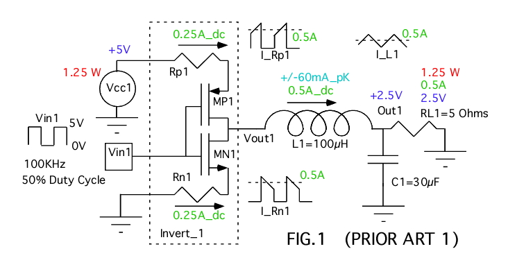
Start off looking at a simplified DC to DC convertor, which is using
a big transistor inverter to drive an inductor with a
50% duty cycle. The inductor L1, capacitor C1 and resistor RL1
are acting like a low pass filter to produce an output voltage
at Out1 which is 50% of the supply voltage Vcc1. The two transistor
MP1 and MN1 are acting like switches. For the sake of
making calculations easier, the effective resistances of MP1, MN1,
and L1 are being modeled at zero.
The inductor will be seeing a DC current of 500mA and an AC
current of +/-60mA. Notice how the inverter is multiplexing the
DC and AC components of the current. The AC component averages out
to zero while the DC component gets 50% multiplexed. The powers
are obeying the laws of thermal dynamics. Load resistor RL1 is
dissipating 1.25W of heat, and Vcc1 is supplying it.
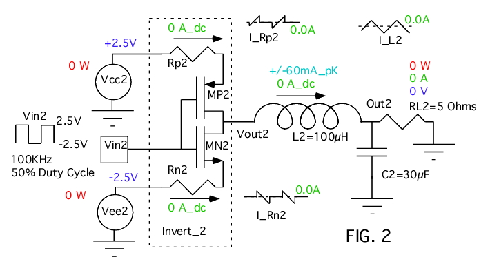
When the circuit of FIG 1 goes dual supply, having RL2 at ground
will mean no DC current flows, and again all the AC currents average
out to zero for the multiplexing of the inverter Invert_1. Since
all resistance except RL2 are modeled at zero, no power is being
dissipated anywhere.
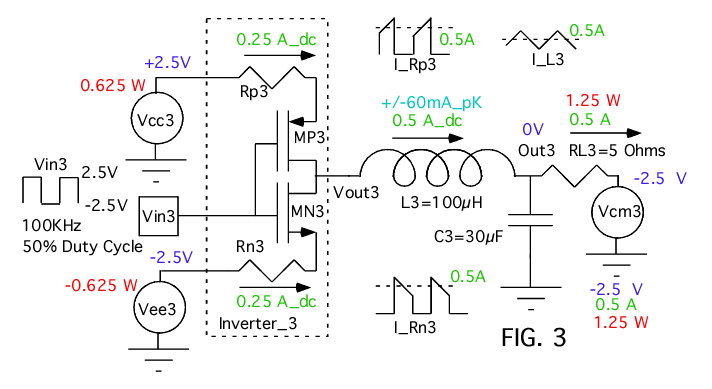
Now add an external common mode power power source Vcm3 to
the circuit of FIG2. With Vcm3 connected to RL3 and set to
-2.5V, then 500mA is flowing through RL3. The Out3 of the
DC to DC converter is acting like a ground. It supplies the
500mA to RL3, but grounds don't dissipate any power. The
external Vcm3 sources is giving out 1.25W of power and RL3
is receiving it all.
It turns out that the DC component of the 500mA is being
multiplexed equally between Vcc3 and Vee3. Now pulling
250mA out of the positive terminal of a 2.5V volt battery
is discharging it by 626mW. But pulling 250mA out of the
negative node of a battery like Vee3 is actually charging
the battery. Again modeling Vcc3 and Vee3 as being like ideal
batteries, the discharge of Vcc3 is being counter by the
charging up of Vee3. So the DC to DC converter output is acting
like a ground. It has 500mA being pull out of it with
out dissipating any power. It is just transferring power from
Vee3 to Vee3.
Now if RL3 where instead connected to Vee3, then both Vee3 and
Vcc3 would be dissipating 625mW of power to add up a 5 volt
supply dissipating 1.25W, just like in FIG 1.
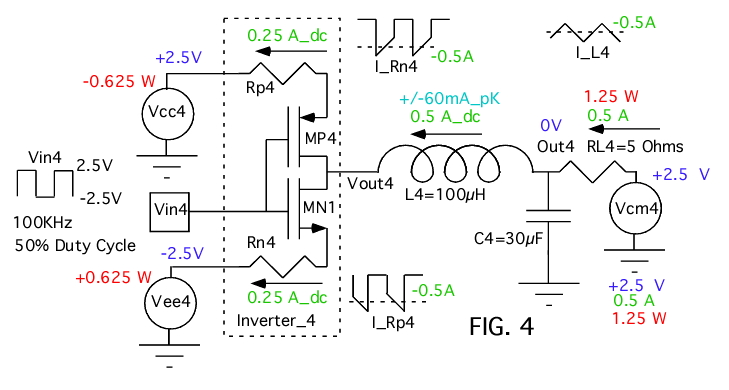
FIG 4 shows that the same is true when Vcm4 is changed to +2.5V.
When the DC to DC converter is acting like a ground, current
into it or out of it should not dissipate any power. If Vcc4
and Vee4 are ideal supplies, then energy is simply being transferred
rather than dissipated.
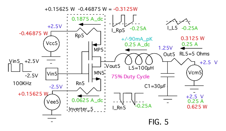
Now take the circuit of FIG 4, and change the duty cycle of the output
to 75%. This will cause Out5 to go to 1.25V. So now RL5 sees
1.25v across it just like Out5. And both RL5 and Out5 of the
DC to DC convertor are conducting 250mA of current. The
external voltage source Vcm5 is being discharged by
625mW. And half of that power is going into RL5. So the DC to
DC convertor is acting like a 5 Ohm resistor in terms of voltage,
current, and even the absorption of power.
Since the output duty cycle is 75%, most of the 250mA current is
going into charging up Vcc5, and some is discharging Vee5. Taking
the supplies together, there is a net charge up of 312.5mW of
power. So the power that the DC to DC convertor is absorbing is
all being transferred to its supplies.
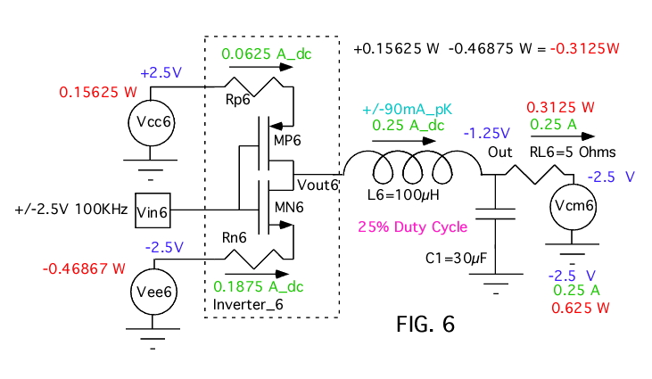
Change the polarity of Vcm6 and the output duty cycle to 25% will
make the DC to DC converting in FIG 6 still look like a 5 Ohm
resistor. And now Vee6 is getting charged up.
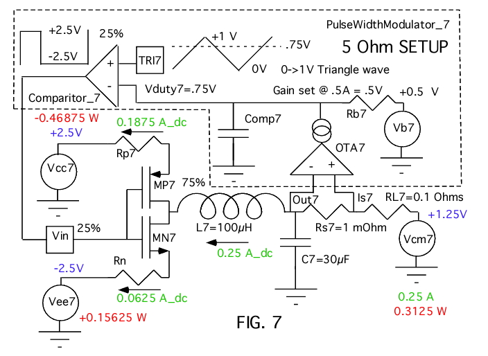
Making the output impedance of a DC to DC convertor behave like
a 5 Ohm resistor simply involves monitoring the output current
and adjusting the duty cycle accordingly. Now the DC to
DC convertor will look like a nice linear resistor. It still
obeys Ohms law and the laws of thermal dynamics. But it does
so by transferring the energy is absorbs to its supplies.
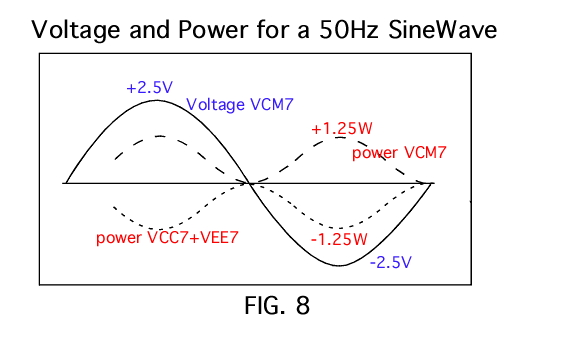
FIG 8 shows Vcm7 as a +/- 2.5V 50Hz AC source, and it power loss will
be as what would be expected of a 5 Ohm load. Monitoring the
net power of the two supplies shows that the AC power is being
transferred to two DC power supplies without a rectifier.
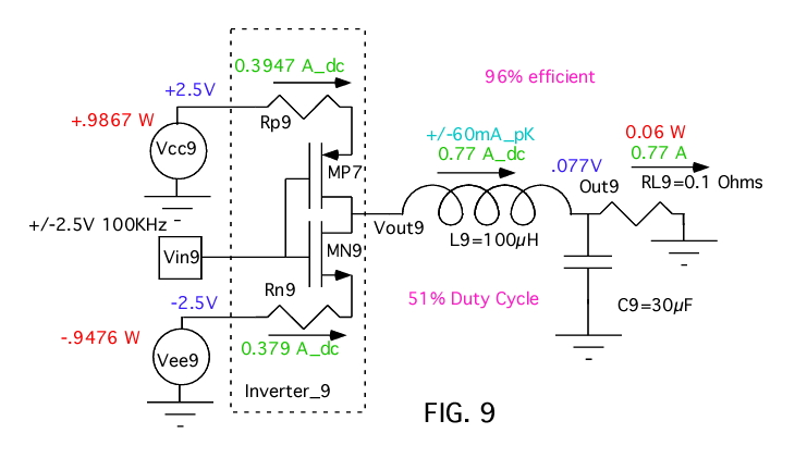
Now while this harvesting resistor can harvest either AC or DC
power, an external DC power source could discharge either
Vcc9 or Vee9. One way to solve this is to just go single supply,
provided the input power will always be in one direction. But an AC
resistor will need two supplies, and as was shown in the circuits
of FIG 3 or FIG 4, FIG 9 shows how it is not hard to shift power
around between two supplies.
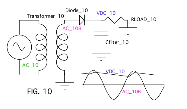
Harvesting AC power to a DC level without a rectifier is a
little unusual. FIG 10 shows the present art as just peak
detecting off the AC waveform. But the fact that the power
is be transferred as a linear resistor has some interesting
applications.
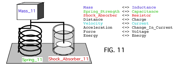
Mechanical systems and electrical systems map very well to
one another. An automobile suspension system is much like a
critically damped LRC network. And a shock absorber, which
can be modeled as a metal disk in a viscous fluid, is serving
as the dampening resistor.
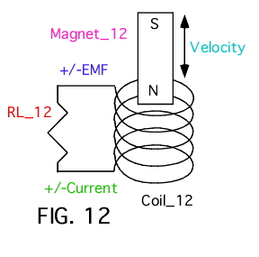
But a magnet moving in and out of a coil which has a resistor
across it can perform the same function. If RL_12 is small
enough, the voltage across Coil_12 which is induced by Magnet_12
moving in and out will produce and opposing magnetic force
to resist movement. So instead of dissipating energy in a
viscous liquid as in Shock_Absorber_11, energy can be dissipated
into RL_12 instead. So now a shock absorber function could be
replaced by an energy harvesting method. This
potential application
has long been recognized. The following are some patents.
1976792_ELECTRIC_SHOCK_ABSORBER
3941402_Electromagnetic_shock_absorber
4032829_Road_shock_energy_converter
5347186_Linear_motion_electric_power_generator
5818132_Linear_motion_electric_power_generator
6952060_Electromagnetic_linear_generator
7357229_Electromagnetic_shock_absorber
7362003_Coil_switching_circuit_for_linear_generation
Some more information concerning the harvesting of shock absorber
energy.
electromagnetic
energy harvester for vehicle suspensions
Regenerative
Shock Absorber
Vehicle
shock absorber recovers energy
A common method of energy
harvesting involves the used of
vibration. When the energy is
periodic, methods such as what
is used for 60Hz AC are perhaps the most convenient.
5578877_Apparatus_for_converting_vibratory_motion
6897573_Electrical_voltage_generating_device
7569952_High_efficiency__inductive_vibration_energy_harvester
Energy
harvesting from vibration
Getting Started with Vibration Energy
Harvesting_V7
The
energy
harvesting resistor, acting like a linear resistor, has
the ability to
dampening/harvest arbitrary energy waveforms. For
example, take a waveform that is random like
ocean waves.
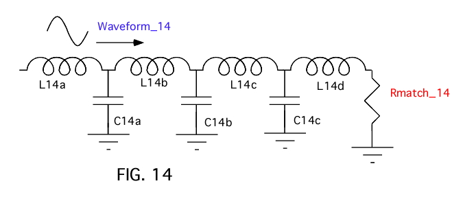
Everything in Nature that can carry a wave of energy
has a characteristic impedance, like a transmission
line.
Ocean waves map mass as L and gravity as C. Could it be possible
to build a buoy array that terminates ocean waves with their
characteristic impedance such at at least 90% of the energy
is absorbed? And could the energy that gets absorbed be
harvested by using shock absorbers techniques?
Having the ability to dampen shock by harvesting energy
is finding many new applications outside of wave energy.
The following are some patents and information.
6982497_Backpack_for_harvesting_electric
7168532_Wave_energy_converter__WEC__with_Magnetic_Braking
Perhaps the best feature about this energy harvesting architecture,
is how easy it is to hook up. This
web page shows the first working
prototype being used to transfer energy bidirectionally between
the AC line and two DC supplies. It so happens that pretty much
any power supply which addresses
power factor correction is in
fact operating like a energy
harvesting resistor. But these
other architectures may not be as simple to build or play
with.
1.3.11_2.44PM
dsauersanjose@aol.com
Don Sauer
http://www.idea2ic.com/