NGSPICE TEMPLATES
==================Switchtest========================

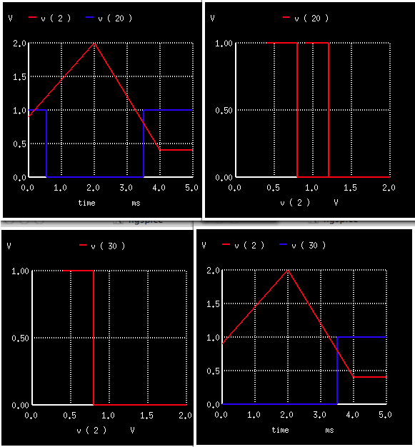
1)Construct two voltages and a current PWL signals
2)Apply these signals to switches
3)Plot input and output waveforms and hysteresis loops
===================================================
Switchtest
* 10
* R10 / s1
* __/\ /\ /\___/ o______
* | \/ \/ _|_ |
* | / v1\ |
* | \___/ |
* | _|_ |
* | /// |
* | |
* | R20 20 / s2 |
* |_/\ /\ /\___/ o_______|
* | \/ \/ _|_ |
* _________| / v2\ |
* _|_ | \___/ |
* /v4 \ | _|_ |
* \___/ | /// |
* _|_ | |
* /// | R30 30 / s3 |
* |__/\ /\ /\___/ON o______|
* | \/ \/ _|_ |
* | / v3\ |
* | \___/ |
* | _|_ |
* | /// |
* | |
* | |
* | 40 |
* | R40 / w1 |
* |___/\ /\ /\___/ o_____|
* \/ \/ |
* _ _ R40 |
* _______/ \/ \____/\ /\ /\_|
* _|_ \_/\_/ \/ \/ _|_
* /// ///
*
.tran 2us 5ms
v1 1 0 DC 0.0 PWL(0 0 2e-3 2 4e-3 0)
v2 2 0 DC 0.0 PWL(0 0.9 2e-3 2 4e-3 0.4 )
i 3 3 0 DC 0.0 PWL(0 0 2e-3 2m 4e-3 0)
v4 4 0 DC 2.0
r3 3 33 10k
vm3 33 0 dc 0 $ <--- measure t h e c u r r e n t
r10 4 10 10k
r20 4 20 10k
r30 4 30 10k
r40 4 40 10k
*
s1 10 0 1 0 switch1 OFF
s2 20 0 2 0 switch1 OFF
s3 30 0 2 0 switch1 ON
.model switch1 sw vt =1 vh =0.2 ron =1 roff =10k
*
w1 40 0 vm3 wswitch1 off
.model wswitch1 csw it =1m ih =0.2m ron =1 roff =10k
*
.control
run
plot v ( 1 ) v ( 10 )
plot v ( 10 ) vs v ( 1 ) $ <-- get hysteresis loop
plot v ( 2 ) v ( 20 ) $ <--- differentinitial values
plot v ( 20 ) vs v ( 2 ) $ <-- gethysteresis loop
plot v ( 2 ) v ( 30 ) $ <--- different initial values
plot v ( 30 ) vs v ( 2 ) $ <-- get hysteresis loop
plot v ( 40 ) vs vm3#branch $ <--- current controlled sitch hysteresis
.endc
.end
* source /Users/don_sauer/Downloads/SI_Lib/Tests.cir
=====================END_OF_SPICE=======================
==============Non_linear_with_frequency_resistor===========
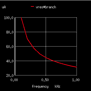
1)Define a B sources using the built in Hertz variable
2)Define a subcircuit nlres using the built in Hertz variable
3)Apply a parameter rb=rbase to nlres
4)Define function check using the vecmax function
5)Use the function check and the built in variable frequency with an if control
6)Plot AC output vres#branch
=================================================================
Non_linear_with_frequency_resistor
*
* Fx
* ___ _ _ ___ _|_ _|_ _|_
* |pos|_/ \/ \_|neg| / B1\ / B2\ / B3\
* |___| \_/\_/ |___| \___/ \___/ \___/
* R2 | | _| _|_ _|_
* _/\ /\ /\___ 2 Vx |_ // /// ///
* | \/ \/ _|_ |
* _|_ / vx\ | Xres
* /// \___/ 1 | 33 _/\ /\ /\__ 10
* |__________| | \/ \/ |
* _|_ _|_ _|_
* / Bx\ / V1\ /Vre\
* \___/ \___/ \___/
* _|_ _|_ _|_
* /// /// ///
*
* -1/{ rb }/sqrt(HERTZ)*v(pos ,neg)
*
B1 1 0 V = hertz*v(33)
B2 2 0 V = v(33)*hertz
b3 3 0 V = 6.283e3/(hertz+6.283e3)*v(33)
V1 33 0 DC 0 AC 1
Xres 33 10 nlres rb =1k
Vres 10 0 DC 0
.Subckt nlres pos neg rb= rbase
Bx 1 0 v = -1/{ rb }/sqrt(HERTZ)*v(pos ,neg)
Vx 2 1 DC 0Volts
Rx 2 0 1
Fx pos neg Vx 1
.ends
.control
define check (a , b) vecmax(abs( a - b ))
ac lin 10 100 1k
print v(1) v(2) v(3)
if check( v (1),frequency) < 1e-12
echo " INFO: ok "
end
plot vres#branch
.endc
.end
* ngspice
* source /Users/don_sauer/Downloads/SI_Lib/Non_linear_resistor.cir
=====================END_OF_SPICE=======================
ngspice 3 -> source /Users/don_sauer/Downloads/SI_Lib/Non_linear_resistor.cir
Circuit: non_linear_resistor
Doing analysis at TEMP = 27.000000 and TNOM = 27.000000
No. of Data Rows : 10
non_linear_resistor
AC Analysis Sat Mar 30 14:42:05 2013
--------------------------------------------------------------------------------
Index frequency v(1)
--------------------------------------------------------------------------------
0 1.000000e+02 1.000000e+02, 0.000000e+00
1 2.000000e+02 2.000000e+02, 0.000000e+00
2 3.000000e+02 3.000000e+02, 0.000000e+00
3 4.000000e+02 4.000000e+02, 0.000000e+00
4 5.000000e+02 5.000000e+02, 0.000000e+00
5 6.000000e+02 6.000000e+02, 0.000000e+00
6 7.000000e+02 7.000000e+02, 0.000000e+00
7 8.000000e+02 8.000000e+02, 0.000000e+00
8 9.000000e+02 9.000000e+02, 0.000000e+00
9 1.000000e+03 1.000000e+03, 0.000000e+00
non_linear_resistor
AC Analysis Sat Mar 30 14:42:05 2013
--------------------------------------------------------------------------------
Index frequency v(2)
--------------------------------------------------------------------------------
0 1.000000e+02 1.000000e+02, 0.000000e+00
1 2.000000e+02 2.000000e+02, 0.000000e+00
2 3.000000e+02 3.000000e+02, 0.000000e+00
3 4.000000e+02 4.000000e+02, 0.000000e+00
4 5.000000e+02 5.000000e+02, 0.000000e+00
5 6.000000e+02 6.000000e+02, 0.000000e+00
6 7.000000e+02 7.000000e+02, 0.000000e+00
7 8.000000e+02 8.000000e+02, 0.000000e+00
8 9.000000e+02 9.000000e+02, 0.000000e+00
9 1.000000e+03 1.000000e+03, 0.000000e+00
non_linear_resistor
AC Analysis Sat Mar 30 14:42:05 2013
--------------------------------------------------------------------------------
Index frequency v(3)
--------------------------------------------------------------------------------
0 1.000000e+02 9.843334e-01, 0.000000e+00
1 2.000000e+02 9.691501e-01, 0.000000e+00
2 3.000000e+02 9.544281e-01, 0.000000e+00
3 4.000000e+02 9.401466e-01, 0.000000e+00
4 5.000000e+02 9.262863e-01, 0.000000e+00
5 6.000000e+02 9.128287e-01, 0.000000e+00
6 7.000000e+02 8.997566e-01, 0.000000e+00
7 8.000000e+02 8.870535e-01, 0.000000e+00
8 9.000000e+02 8.747042e-01, 0.000000e+00
9 1.000000e+03 8.626939e-01, 0.000000e+00
info: ok
ngspice 4 ->
===============Parameter_to_pwl_Bsource==========================
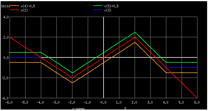
1)Define many x and y parameters
2)Apply the x and y parameters to B sources in PWL format
3)Do a DC sweep
4)Plot outputs with various offsets
=================================================================
Parameter_to_pwl_Bsource
.param x0=-4 y0=0
.param x1=-2 y1=2
.param x2=2 y2=-2
.param x3=4 y3=1
.param xx0= x0-1
.param xx3= x3+1
Vin 1 0 DC=0V
R 1 0 2
Btest2 2 0 I = pwl( v(1),x0,y0,x1,y1,x2,y2,x3,y3)
Btest3 3 0 I = ( v(1)<x0) ? y0:(v(1)<x3) ? pwl(v(1),x0,y0,x1,y1,x2,y2,x3,y3):y3
Btest4 4 0 I = pwl( v(1), xx0,y0,x0,y0,x1,y1,x2,y2,x3,y3,xx3,y3)
Btest5 5 0 I = pwl(-2*i(Vin),xx0,y0,x0,y0,x1,y1,x2,y2,x3,y3,xx3,y3)
Rint2 2 0 1
Rint3 3 0 1
Rint4 4 0 1
Rint5 5 0 1
.control
dc Vin -6 6 0.2
plot v(2) v(3) v(4)-0.5 v(5)+0.5
.endc
.end
* ngspice
* source /Users/don_sauer/Downloads/SI_Lib/pwlfunctioninBsource.cir
=====================END_OF_SPICE=======================
=================VCCS_examples============================
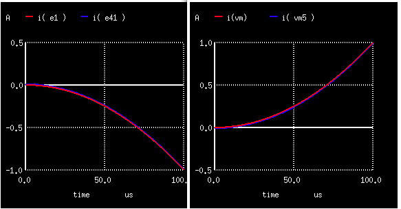
1)Create two parameters Vi and Offs
2)Apply parameters to devices
3)The set noaskquit will allow a quit without save
4)Transient simulate and plot outputs
=================================================================
VCCS_examples
.param Vi = 1
.param Offs = 0.01*Vi
B21 int1 0 V = V( 3 )*V( 3 )
G1 21 22 int1 0 1
vm 22 0 dc 0
R21 21 0 1
G51 55 225 cur = V( 3 )*V(3)-Offs
vm5 225 0 dc 0
R51 55 0 1
B31 int2 0 V = V( 3 )*V( 3 )
E1 1 0 int2 0 1
R1 1 0 1
E41 4 0 vol = V( 3 )*V(3)-Offs
R4 4 0 1
V1 3 0 PWL(0 0 100u {Vi } )
.control
set noaskquit
tran 10n 100u uic
plot i( E1 ) i( E41 )
plot i( vm ) i( vm5 )
.endc
.end
* ngspice
* source /Users/don_sauer/Downloads/SI_Lib/VCCS_exmaples.cir
=====================END_OF_SPICE=======================
===================Simple_PLL=================
1)Create VT as a PWL time voltage ramp
2)Create VIN as a sinwave source running off VT
3)Create LOSC like VIN, set to be phase modulated by voltage VPHASE
4)Multiply and low pass filter LOSC to create LPASS
5)Voltage LPASS is meant to by used as a frequency modulate signal
6)FM signal LPASS is translated to a PM signal VPHASE by integration
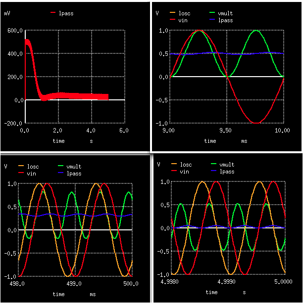
7)Transient simulation will show how LPASS settles to zero
8)Plot all the voltages at various points in time
9)Only eight lines of spice code needed to make a functional PLL
=================================================================
Simple_PLL
* ______________________________
* | \
* | V = sin(2*PI*Fre*T+IntFM*T) \
* VMULT RLP LPASS | ^ \
* ____/\ /\ /\_______| RINT VPHAS /|\ \
* _|_ \/ \/ | | __/\ /\ /\_____ _ _ _| \_ LOSC
* VIN / \ _|_ | \/ \/ _|_ / |
* ____|\/ \/ \ CLP ___ | FM ___ SYSTEM / |
* _|_ |/\ /\ / _|_ | CINT _|_ MODELED / |
* /_ \ \___/ BMULT /// | /// VCO / |
*// \ \ ^ |_____________________________/ |
*\ \// /_\ |
* \___/ |_________________________________________________________|
* _|_
* /// WinSpice/MacSpice 2.19.11_6.58PM dsauersanjose@aol.com
*
*=========All_System_Modeled_PLL==================
VT VT 0 DC 0 PWL( 0 0 10 10 )
BVIN VIN 0 V = sin( 6.28*1000*V(VT) )
BLOSC LOSC 0 V = sin( 6.28*1000*V(VT) + 10*V(VPHAS)*V(VT) )
BMULT VMULT 0 V = V(VIN)*V(LOSC)
RLP VMULT LPASS 1k
CLP LPASS 0 1.6u
RINT LPASS VPHAS 1meg
CINT VPHAS 0 1u
.control
*set pensize = 2
tran .01m 5 0 .01m
plot lpass
plot vin lpass losc vmult xlimit 9m 10m
plot vin lpass losc vmult xlimit 498m 500m
plot vin lpass losc vmult xlimit 4998m 5000m
.endc
.end
*display
.endc
.end
* source /Users/don_sauer/Downloads/SI_Lib/Tests.cir
=====================END_OF_SPICE=======================
=================PINCH_RESISTOR========================
1)Create Vtest as a PWL voltage ramp
2)Create Rpinch as the voltage node subcircuit
3)Use VRset to set the zero volt resistance.
4)Assume the tub is connected to Vtest as in drawing
5)Use B sources to define the V to I relationship.
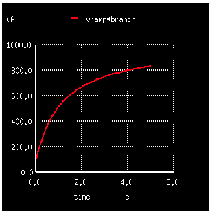
6)Plot the current versus voltage to see the pinchoff effect.
=================================================================
PINCH_RESISTOR
*
* XRpinch
* Vtest ________
* _____|_/\ /\ /\_
* _|__ \/ \/ _|_
* /_ \ : ///
* // \ \ :
* \ \_// : Rset
* \____/ :./\ /\ /\_
* _|_ \/ \/ _|_
* /// VRset ///
* Vramp
* Attach Pin 2 to highest voltage
*
* ________________________________________________________
* / _____________________ Nepi /
* / ____________ /..................../_______________ /
* / / ________ / / ________ / /
* / / /____ 1 / / 2 / /____ 3 / / /
* / / //___/| / / / //___/| / / /
* / / / |___|// / / / |___|// / /
* _/_/_/_______/___/____________________/_____/_______/_/__/___
* | | | p+imp | | n+imp | | p+imp | | |
* | \ \_____/ \___________________/ base \_____/ / |
* | \______________________________________________/ | Psub
* | _ _ _ _ _ _ _ _ _ _ _ _ _ _ _ _ _ _ _ _ _ _ _ _ _ _ |
* |/ N BURIED LAYER \|
* \ _ _ _ _ _ _ _ _ _ _ _ _ _ _ _ _ _ _ _ _ _ _ _ _ _ _ /
* P-Substrate
*
Vramp Vtest 0 PWL( 0 0.1 5 5.0)
XRpinch Vtest 0 VRset Rpinch
Rset VRset 0 1k
.control
tran 100m 5 0 100m
plot -vramp#branch
.endc
.SUBCKT Rpinch INP INN VRS
Isen VRS 0 -1u
Bpinc INP INN I= 1u*(v(INP)-v(INN))/(v(VRS) + v(VRS)*(v(INP)-v(INN)) )
.ENDS Rpinch
.end
* source /Users/don_sauer/Downloads/SI_Lib/Tests.cir
=====================END_OF_SPICE=======================
===================test_pz_sanity===============================
1)Apply an ac current source to a unity LRC circuit
2)Suppress printing of statistics of the Initial Transient Solution using .options noacct
3)Do PZ in terms of current and poles
4)print out the two poles
5)Do for various values of R
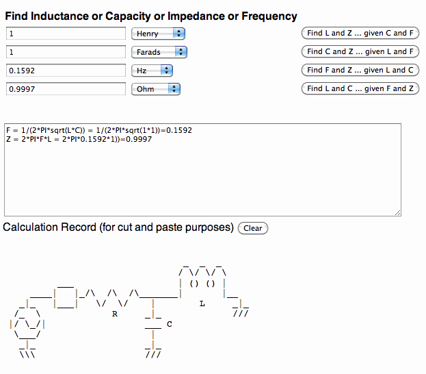
6)Note the frequency is in terms of 1 rad/sec which is 0.159Hz.
7)Sanity check using the web page at http://www.idea2ic.com/PlayWithJavascript/L_C_R_F.html
=================================================================
test_pz_sanity
* Iin
* _ _
* _______/ \/ \_____
* _|_ \_/\_/ | _ _ _
* /// | / \/ \/ \
* 1 | | () () |
* _/\ /\ /\____|__| |__
* _|_ \/ \/ | L _|_
* /// R _|_ ///
* ___ C
* |
* _|_
* ///
iin 1 0 ac
r 1 0 1
c 1 0 1
l 1 0 1
.print pz all
.options noacct
.control
pz 1 0 2 0 cur pol
print pole(1) pole(2)
.endc
.end
* source /Users/don_sauer/Downloads/SI_Lib/Tests.cir
=====================END_OF_SPICE=======================
r 1 0 .100
c 1 0 1
l 1 0 1
pole(1) = -9.89898e+00,0.000000e+00
pole(2) = -1.01021e-01,0.000000e+00
r 1 0 .3
c 1 0 1
l 1 0 1
pole(1) = -3.00000e+00,0.000000e+00
pole(2) = -3.33333e-01,0.000000e+00
r 1 0 .501
c 1 0 1
l 1 0 1
pole(1) = -9.98004e-01,6.315087e-02
pole(2) = -9.98004e-01,-6.31509e-02
r 1 0 1
c 1 0 1
l 1 0 1
pole(1) = -5.00000e-01,8.660254e-01
pole(2) = -5.00000e-01,-8.66025e-01
r 1 0 100
c 1 0 1
l 1 0 1
pole(1) = -5.00000e-03,9.999875e-01
pole(2) = -5.00000e-03,-9.99987e-01
r 1 0 100k
c 1 0 1
l 1 0 1
pole(1) = -5.00000e-06,1.000000e+00
pole(2) = -5.00000e-06,-1.00000e+00
====================NPN_Ftau_15uu_TF==========================
1)Using an ac current source applied to the emitter of an NPN
2)At ftau, the magnitude of AC current in the base equals that of the collector
3)Do a foreach for five levels of emitter current myic
3)Add a foreach mytf for three levels of TF for the NPNV model
4)Do AC from 10KHz to 100Ghz each time
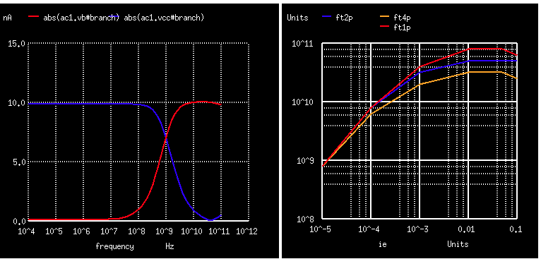
5)Compose five element arrays ie, ft1p, ft2p, ft4p to use for waveforms
6)Fill array ie with the five levels of emitter current myic
7)Fill arrays ft1p, ft2p, ft4p the found ftau levels
8)Plot ft1p, ft2p, ft4p versus ie to see the result
9)Use The destroy all clears all the plots.
=================================================================
NPN_Ftau_15uu_TF
*
* _________
* b _| c _|_
* ___|'QN1 /vcc\
* _|_ |`->e \___/
* /vb \ | |
* \___/ _|_ _|_
* | / _ \i1 ///
* _|_ \/ \/
* /// /\_/\
* \___/
* _|_
* ///
*
.OPTIONS GMIN=1e-15 METHOD=gear ABSTOL=1e-15 TEMP=27 srcsteps = 1 gminsteps = 1
VCC C 0 DC 5V
QN1 C B E NPNV
VB B 0 0
I1 E 0 DC 100u AC .01u
.control
destroy all
foreach mytf 1p 2p 4p
foreach myic 10u 100u 1e-3 10e-3 50e-3 100e-3
alter i1 = $myic
altermod npnv tf = $mytf
ac dec 10 10k 100g
end
end
echo $plots
plot abs(ac1.vb#branch) abs(ac1.vcc#branch)
plot abs(ac2.vb#branch) abs(ac2.vcc#branch)
compose ie start = 0 stop = 5 step =1
compose ft1p start = 0 stop = 5 step =1
compose ft2p start = 0 stop = 5 step =1
compose ft4p start = 0 stop = 5 step =1
let index = 0
while ( index < length(abs(ac1.vb#branch)) )
if ( abs(ac1.vcc#branch[index]) > abs(ac1.vb#branch[index]) )
let ft1p[0] = mag(frequency[index] )
let ie[0] = 10e-6
end
if ( abs(ac2.vcc#branch[index]) > abs(ac2.vb#branch[index]) )
let ft1p[1] = mag(frequency[index] )
let ie[1] = 100e-6
end
if ( abs(ac3.vcc#branch[index]) > abs(ac3.vb#branch[index]) )
let ft1p[2] = mag(frequency[index] )
let ie[2] = 1e-3
end
if ( abs(ac4.vcc#branch[index]) > abs(ac4.vb#branch[index]) )
let ft1p[3] = mag(frequency[index] )
let ie[3] = 10e-3
end
if ( abs(ac5.vcc#branch[index]) > abs(ac5.vb#branch[index]) )
let ft1p[4] = mag(frequency[index] )
let ie[4] = 50e-3
end
if ( abs(ac6.vcc#branch[index]) > abs(ac6.vb#branch[index]) )
let ft1p[5] = mag(frequency[index] )
let ie[5] = 100e-3
end
if ( abs(ac7.vcc#branch[index]) > abs(ac7.vb#branch[index]) )
let ft2p[0] = mag(frequency[index] )
let ie[0] = 10e-6
end
if ( abs(ac8.vcc#branch[index]) > abs(ac8.vb#branch[index]) )
let ft2p[1] = mag(frequency[index] )
end
if ( abs(ac9.vcc#branch[index]) > abs(ac9.vb#branch[index]) )
let ft2p[2] = mag(frequency[index] )
end
if ( abs(ac10.vcc#branch[index]) > abs(ac10.vb#branch[index]) )
let ft2p[3] = mag(frequency[index] )
end
if ( abs(ac11.vcc#branch[index]) > abs(ac11.vb#branch[index]) )
let ft2p[4] = mag(frequency[index] )
end
if ( abs(ac12.vcc#branch[index]) > abs(ac12.vb#branch[index]) )
let ft2p[5] = mag(frequency[index] )
end
if ( abs(ac13.vcc#branch[index]) > abs(ac13.vb#branch[index]) )
let ft4p[0] = mag(frequency[index] )
let ie[0] = 10e-6
end
if ( abs(ac14.vcc#branch[index]) > abs(ac14.vb#branch[index]) )
let ft4p[1] = mag(frequency[index] )
end
if ( abs(ac15.vcc#branch[index]) > abs(ac15.vb#branch[index]) )
let ft4p[2] = mag(frequency[index] )
end
if ( abs(ac16.vcc#branch[index]) > abs(ac16.vb#branch[index]) )
let ft4p[3] = mag(frequency[index] )
end
if ( abs(ac17.vcc#branch[index]) > abs(ac17.vb#branch[index]) )
let ft4p[4] = mag(frequency[index] )
end
if ( abs(ac18.vcc#branch[index]) > abs(ac18.vb#branch[index]) )
let ft4p[5] = mag(frequency[index] )
end
let index = index +1
end
*print ft1p[0] ft1p[1] ft1p[2] ft1p[3] ft1p[4] ft1p[5]
plot ft1p ft2p ft4p vs ie loglog
.endc
.MODEL NPNV NPN(
+ IS=10.15e-18 NF=1.0 BF=89 VAF=107 IKF=.4
+ NR=1.006 BR=0.4822 VAR=4.286 IKR=0.0002472
+ ISE=9.15E-17 NE=2
+ ISC=1E-21 NC=2
+ RB=12 RBM=3 IRB=.1
+ RE=2 RC=33
+ CJE=37e-15 VJE=0.75 MJE=0.35
+ CJC=45E-15 VJC=0.6399 MJC=0.3531
+ CJS=2.939E-15 VJS=0.3488 MJS=0.1813 XCJC=0.4201
+ TF=1e-12 XTF=1 VTF=1.5 ITF=.8
+ TR=5.9e-9 FC=0.5 PTF=30
+ KF=1.000E-16 AF=1
+ XTB=2 EG=1.11 XTI=5 TNOM=25 )
.end
* source /Users/don_sauer/Downloads/SI_Lib/Tests.cir
=====================END_OF_SPICE=======================
==========================Model_internals===================================
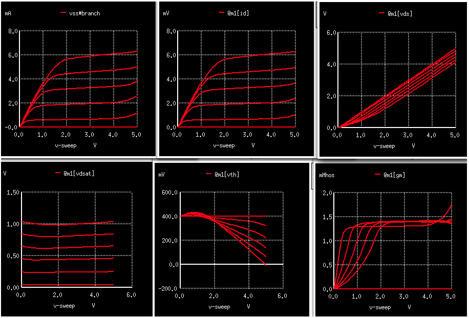
1)Do a normal curve tracer DC sweep on an NMOS transistor m1
2)The vss#branch has the normal output
3)A print @m1 will print out the parameter available for viewing
4)The simulated parameters can be plotted using the format of @m1[id]
=================================================================
Model_internals
* _______
* __| d1 _|_
* ||____ /Vdd\
* g1 __|| | \___/
* _|_ ||-> | |
* /Vsg\ |_| _|_
* \___/ _|_ ///
* | /Vss\
* _|_ \___/
* /// |
* _|_
* ///
*
vdd vdd 0 2.0
vss vss 0 0
vsig g1 vss 1
m1 vdd g1 vss vss nmosc w=1e-5 l=3.5e-007
.control
dc Vdd 0 5 .1 Vsig 0 5 1
plot vss#branch
save @m1[id] @m1[vds] @m1[vdsat] @m1[vth] @m1[gm]
dc Vdd 0 5 .1 Vsig 0 5 1
plot @m1[id]
plot @m1[vds]
*plot @m1[vgs]
plot @m1[vdsat]
plot @m1[vth]
plot @m1[gm]
*print @m1 $ to view model parameters
.endc
* source /Users/don_sauer/Downloads/SI_Lib/Tests.cir
.model NMOSC NMOS
+ Level= 8 Tnom=27.0 version =3.3.2
*------------------Process-----------------------------------------------
+ tox=160e-10 xj=0.25e-06 nch=0.5e+17
*------------------V_threshold-------------------------------------------
+ vth0=0.72 nlx=0.12e-06
*------------------Bulk--------------------------------------------------
+ k1=1.04 k2=-1.209E-01
*------------------mobility----------------------------------------------
+ u0=678 ua=8.964e-10
+ ub=1.472e-18 uc=-4.441E-17 vsat=86000
*------------------Subthresshold-----------------------------------------
+ nfactor=1.8
+ cit=-5.0E-04 voff=-7.862E-02
+ eta0=4.441e-16 etab=-2.E-01 dsub=0.7
*------------------Hot electrons-----------------------------------------
+ alpha0=1.61e-05 beta0=36.68
*------------------VAF---------------------------------------------------
+ lint=.12e-06 pclm=.19 pscbe1=3.79e+08 pscbe2=9.4e-05
+ delta=0.01655 pvag=0.4484
*------------------Bulk_diode--------------------------------------------
+ js=5.858e-08
*------------------Resistance--------------------------------------------
+ rsh=70 rdsw=375
+ wr=0.7586 prwb=0 prwg=-4.441E-17
*------------------Capacitance-------------------------------------------
+ cj=0.0002424 cjsw=2.73e-10 mj=0.3551 mjsw=0.3873
+ cgso=9e-13 cgdo=9e-13 cgbo=7e-10
+ cdsc=-2.4E-4 cdscd=-1.506E-01 cdscb=-2.219E-04
+ pb=0.5614 pbsw=0.8 xpart=0
+ dlc=5e-08 dwc=1.5e-07
*------------------BulkChargeEffect--------------------------------------
* a0=0.7 a1=0 a2=1 ags=0.05583
* b0=6.305e-08 b1=6.579e-08 keta=-1.531E-02
*------------------ShortChannel------------------------------------------
+ dvt0=2.2 dvt1=0.53 dvt2=-1.521E-01 drout=0.76
+ pdiblcb=.4 pdiblc1=0.00886 pdiblc2=0.00029
*------------------NarrowChannel-----------------------------------------
+ w0=2.6e-04 wint=0.16e-06
+ ww=-9.525E-14 wwn=1.0
+ dvt0w=0 dvt1w=5.3e6 dvt2w=-1.E-01
+ k3=2.53 k3b=-5 dwg=0 dwb=0
*------------------Noise-------------------------------------------------
* af=1 kf=1e-28 ef=0.95
*------------------Temperature-------------------------------------------
* pvsat=0 ute=-1.258E+00 kt1=-3.85E-01
* kt1l=0 kt2=-3.098E-02 ua1=5.705e-09
* ub1=-1.147E-17 uc1=-1.302E-01 at=20380
* prt=-3.287E+02 lk1=0 lk2=0
* lvsat=0 la0=0 lags=0 lute=0
.end
* source /Users/don_sauer/Downloads/SI_Lib/Tests.cir
=====================END_OF_SPICE=======================
ngspice 9 -> @m1 $ to view model parameters
@m1: no such command available in ngspice
ngspice 10 -> print @m1 $ to view model parameters
Vds [vds]=4.11659
Vgs [vgs]=4.55899
Vbs [vbs]=-0.441014
Ids [id]=0.0063002
Vth [vth]=-0.00673526
Vdsat [vdsat]=1.03402
Gds [gds]=0.000302297
Gm [gm]=0.00139937
Gmb [gmbs]=-0.00150947
AC NQS model selector [acnqsmod]=0
Non-quasi-static model selector [nqsmod]=0
ERROR: enumeration value `CP_BOOL' or `CP_LIST' not handled in vec_get
Aborting...
Fatal error in NGSPICE - Return
================RC_3dB=====================================
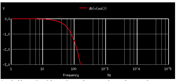
1)Finding the 3dB point of a AC plot of a RC lowpass
2)Find size of the frequency array after simulation
3)Use a repeat 39 to step through all the array values
4)Use if statement find the frequency where the dB value is -3dB
5)Print of the found value using the $&f format
6)Sanity check the meas AC statement
=================================================================
RC_3dB
*
*
* R1
* VIN ___
* _____/\ /\ /\________|OUT|
* | \/ \/ | |___|
* _|__ |
* /_ \ _|_
* // \ \ ___ C1 Find 3dB freq
* \ \_// |
* \____/ _|_
* _|_ ///
* ///
*
*
.OPTIONS GMIN=1e-15 METHOD=gear ABSTOL=1e-15 temp=27
VIN IN 0 DC 0V AC 1V
R1 IN OUT 1k
C1 OUT 0 1u
.control
run
ac dec 10 1 10khz
plot db(v(out)) ylimit -3 0 title Find_R_C_3dB
let n = 0
let f = 0
repeat 39
let n = n+1
if ( db( out[n]) >-3)
let f = mag(frequency[n])
endif
endrepeat
echo "3dB point = $&f Hz"
meas ac freq_3d_at WHEN vdb(out) =-3
.endc
.end
* source /Users/don_sauer/Downloads/SI_Lib/Tests.cir
=====================END_OF_SPICE=======================
3db point = 158.489 hz
freq_3d_at = 1.587800e+02
======================BSIM_NMOS_Caps=================================
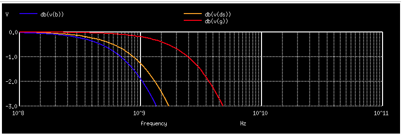
1)Sanity checking the stray capacitance to NMOSC device.
2)Find size of the frequency array or length(g)
3)Use a while (ii < length(g) )to step through all the array values
4)Use if statement find the frequency where the dB value is -3dB
5)Print of the found value using the $&f format
6)Note schematic expected model values included with spice file
=================================================================
BSIM_NMOS_Caps
*
* IN
* ___________/\ /\ /\___________________________________
* | RG 10K \/ \/ |
* | |
* | |
* |__________/\ /\ /\_____________ |
* | RDS 10K \/ \/ | |
* | | |
* | | |
* |__________/\ /\ /\__ | 9.1fF |
* | RB 10K \/ \/ | | |
* | |B |DS G | 3.3fF
* | |12fF | |
* _|__ VIN MB | MDS | MG |
* /_ \ _________| ___| ___ |
* // \ \ | |_ | | |_ | |_ |
* \ \_// | ||__| | ||_ | ||__|
* \____/ __/|\____|| __/|\____|| | _/|\____||
* _|_ | | <-|| | | <-|| | | | <-||
* /// | |___| | |___| | | |___|
* | | | | |
* |________________|____________|___|______|
* _|_
* ///
.OPTIONS GMIN=1e-15 METHOD=gear ABSTOL=1e-15 temp=27
VIN IN 0 DC 0V AC 1V
RG G IN 10k
RDS DS IN 10k
RB B IN 10k
MB B B B 0 NMOSC W=3u L=1u AD=7p AS=7p PD=10u PS=10u
MDS DS 0 DS 0 NMOSC W=3u L=1u AD=7p AS=7p PD=10u PS=10u
MG 0 G 0 0 NMOSC W=3u L=1u AD=7p AS=7p PD=10u PS=10u
.control
op
ac dec 50 100Meg 10ghz
plot db(v(g)) db(v(b)) db(v(ds)) ylimit -3 0
set stopp = length(g)
*compose fg start = 0 stop = $&stopp step =1
let fg = 0
let fb = 0
let fds = 0
let ii = 0
while (ii < length(g) )
if (db(g)[ii] > -3 )
let fg = mag( frequency[ii] )
end
if ( db(b)[ii] > -3 )
let fb = mag( frequency[ii] )
end
if (db(ds)[ii] > -3 )
let fds = mag( frequency[ii] )
end
let ii = ii + 1
end
print fg fb fds
let cg = 1/(6.28e4*fg)
echo "3dB point f = $&fg Hz cg = $&cg"
let cb = 1/(6.28e4*fb)
echo "3dB point f = $&fb Hz cb = $&cb"
let cds = 1/(6.28e4*fds)
echo "3dB point f = $&fds Hz cds = $&cds"
let cbs = cds/2
let cgb = cb - cds
let cgs = (cg - cgb)/2
echo "cbs = cbd = $&cbs"
echo "cgs = cgd = $&cgs"
echo "cgb = $&cgb"
.endc
* ngspice
* source /Users/don_sauer/Downloads/SI_Lib/Tests.cir
*model = bsim3v3
*Berkeley Spice Compatibility
* Lmin= .35 Lmax= 20 Wmin= .6 Wmax= 20
.model NMOSB NMOS
+Level= 8 version=3.2.2
+Tnom=27.0
+Nch= 2.498E+17 Tox=9E-09 Xj=1.00000E-07
+Lint=9.36e-8 Wint=1.47e-7
+Vth0= .6322 K1= .756 K2= -3.83e-2 K3= -2.612
+Dvt0= 2.812 Dvt1= 0.462 Dvt2=-9.17e-2
+Nlx= 3.52291E-08 W0= 1.163e-6
+K3b= 2.233
+Vsat= 86301.58 Ua= 6.47e-9 Ub= 4.23e-18 Uc=-4.706281E-11
+Rdsw= 650 U0= 388.3203 wr=1
+A0= .3496967 Ags=.1 B0=0.546 B1= 1
+ Dwg = -6.0E-09 Dwb = -3.56E-09 Prwb = -.213
+Keta=-3.605872E-02 A1= 2.778747E-02 A2= .9
+Voff=-6.735529E-02 NFactor= 1.139926 Cit= 1.622527E-04
+Cdsc=-2.147181E-05
+Cdscb= 0 Dvt0w = 0 Dvt1w = 0 Dvt2w = 0
+ Cdscd = 0 Prwg = 0
+Eta0= 1.0281729E-02 Etab=-5.042203E-03
+Dsub= .31871233
+Pclm= 1.114846 Pdiblc1= 2.45357E-03 Pdiblc2= 6.406289E-03
+Drout= .31871233 Pscbe1= 5000000 Pscbe2= 5E-09 Pdiblcb = -.234
+Pvag= 0 delta=0.01
+ Wl = 0 Ww = -1.420242E-09 Wwl = 0
+ Wln = 0 Wwn = .2613948 Ll = 1.300902E-10
+ Lw = 0 Lwl = 0 Lln = .316394
+ Lwn = 0
+kt1=-.3 kt2=-.051
+At= 22400
+Ute=-1.48
+Ua1= 3.31E-10 Ub1= 2.61E-19 Uc1= -3.42e-10
+Kt1l=0 Prt=764.3
.model NMOSC NMOS
+ Level= 8 Tnom=27.0 version=3.2.2
*------------------Process-----------------------------------------------
+ tox=160e-10 xj=0.25e-06 nch=0.5e+17
*------------------V_threshold-------------------------------------------
+ vth0=0.72 nlx=0.12e-06
*------------------Bulk--------------------------------------------------
+ k1=1.04 k2=-1.209E-01
*------------------mobility----------------------------------------------
+ u0=678 ua=8.964e-10
+ ub=1.472e-18 uc=-4.441E-17 vsat=86000
*------------------Subthresshold-----------------------------------------
+ nfactor=1.8
+ cit=-5.0E-04 voff=-7.862E-02
+ eta0=4.441e-16 etab=-2.E-01 dsub=0.7
*------------------Hot electrons-----------------------------------------
+ alpha0=1.61e-05 beta0=36.68
*------------------VAF---------------------------------------------------
+ lint=.12e-06 pclm=.19 pscbe1=3.79e+08 pscbe2=9.4e-05
+ delta=0.01655 pvag=0.4484
*------------------Bulk_diode--------------------------------------------
+ js=5.858e-08
*------------------Resistance--------------------------------------------
+ rsh=70 rdsw=375
+ wr=0.7586 prwb=0 prwg=-4.441E-17
*------------------Capacitance-------------------------------------------
+ cj=0.0002424 cjsw=2.73e-10 mj=0.3551 mjsw=0.3873
+ cgso=9e-13 cgdo=9e-13 cgbo=7e-10
+ cdsc=-2.4E-4 cdscd=-1.506E-01 cdscb=-2.219E-04
+ pb=0.5614 pbsw=0.8 xpart=0
+ dlc=5e-08 dwc=1.5e-07
*------------------BulkChargeEffect--------------------------------------
* a0=0.7 a1=0 a2=1 ags=0.05583
* b0=6.305e-08 b1=6.579e-08 keta=-1.531E-02
*------------------ShortChannel------------------------------------------
+ dvt0=2.2 dvt1=0.53 dvt2=-1.521E-01 drout=0.76
+ pdiblcb=.4 pdiblc1=0.00886 pdiblc2=0.00029
*------------------NarrowChannel-----------------------------------------
+ w0=2.6e-04 wint=0.16e-06
+ ww=-9.525E-14 wwn=1.0
+ dvt0w=0 dvt1w=5.3e6 dvt2w=-1.E-01
+ k3=2.53 k3b=-5 dwg=0 dwb=0
*------------------Noise-------------------------------------------------
* af=1 kf=1e-28 ef=0.95
*------------------Temperature-------------------------------------------
* pvsat=0 ute=-1.258E+00 kt1=-3.85E-01
* kt1l=0 kt2=-3.098E-02 ua1=5.705e-09
* ub1=-1.147E-17 uc1=-1.302E-01 at=20380
* prt=-3.287E+02 lk1=0 lk2=0
* lvsat=0 la0=0 lags=0 lute=0
* CG = CGS + CGD + Cox CGS = (CG-Cgb)/2
* CB = CBS + CBD + Cox Cgb = CB -CDS
* CDS = CBS + CBD CBS = CDS/2
**
** SPICE MODEL ___
** __/\ ______| | Source
** CGS | \/ RS |___|
** _____________|__________
** _|_ _|_ _|_ _|_
** Gate ___ / _ \ I_ds \ / ___ CBS 6fF<- (Caps for L/W 1u/2.6u)
** ___ | \/ \/ _V_ |
** | |__| /\_/\ | |_____| ___
** |___| |___ \___/ V ___| |____| | Bulk 10K10F 100p
** | | | | _|_ _|_ |___|
** _|_ |__/|\__||_| ^ ___ |__..no..__
** ___ |2fF|| /_\ | CBD _|_
** |_______|__________|_____| 6fF ^
** CGD CGD | ___ /_\
** |__/\ ______| | Drain _|_
** \/ RD |___| \sub/
** \ /
** <Bulk_hidden = gnd!> V
**
** (G)
** (D) ___|__ (S) (B) (Sub)
** _|_ |______| _|_ _|_ _|_
** ______|___|_|______|_|___|______|___|________|___|__ _
** | | P+ | <++++| P+ | | N+ | | | P+ | Xj
** | \_____/ \_____/ \_____/ | \_____/ _
** | NWELL |
** \______________________________________/
**
**
.end
* source /Users/don_sauer/Downloads/SI_Lib/Tests.cir
=====================END_OF_SPICE=======================
No. of Data Rows : 101
fg = 2.754229e+09
fb = 1.000000e+09
fds = 1.148154e+09
3db point f = 2.75423E+09 hz cg = 5.7815E-15
3db point f = 1E+09 hz cb = 1.59236E-14
3db point f = 1.14815E+09 hz cds = 1.38688E-14
cbs = cbd = 6.93442E-15
cgs = cgd = 1.86339E-15
cgb = 2.05472E-15
======================NPN_GUMMEL=========================================
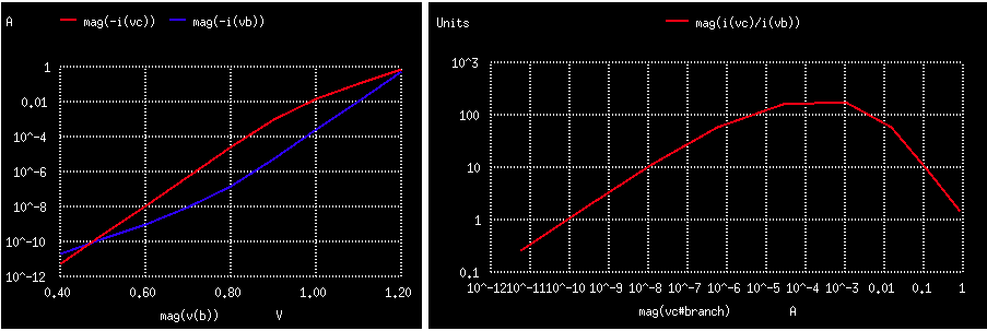
1)Sanity checking NPN device.
2)DC sweep the base voltage
3)Use current of VC and VB to measure collector and base current
4)Plot i(VC) and i(VB) versus base voltage V(b)
5)Plot i(VC) / i(VB) versus collector current
=================================================================
NPN_GUMMEL
* MEASURE IS,ISE,NF,NE,RE,IKF,BETA
*
* ________
* | | VC
* |C _|_
* B _| /2v \
* ____|' npnv \___/
* | |`-> |
* VB _|_ | 0 |
* /.7v\ |________|
* \___/ _|_
* | ///
* _|_
* /// 0 1u
.OPTIONS GMIN=1e-15 METHOD=gear ABSTOL=1e-15
*======== ====== ====== ====== ====== ====== ====== ====== ======
VC C 0 DC 5V
VB B 0 0V
Q1 C B 0 NPNV
.MODEL NPNV NPN(
*==========================================================
+IS=1.1E-18 NF=1.005 BF=220 VAF=130 IKF=5e-03
+ISE=9.15E-15 NE=2
*==========================================================
+CJE=2E-12 CJC=2E-13 CJS=3E-12 TF=.6E-9 )
.control
*DC SOURC1 VSTART VSTOP VSTEP SOURC2 START2 STOP2 STEP2
dc vb .4 1.2 .1
plot mag(-i(vc)) mag(-i(vb)) vs mag(V(b)) ylog title Gummel
plot mag(i(vc)/i(vb)) vs mag(vc#branch) loglog title Beta_vs_IC
.endc
.end
* source /Users/don_sauer/Downloads/SI_Lib/Tests.cir
=====================END_OF_SPICE=======================
=============NMOS_bsim3_SubSanity=================
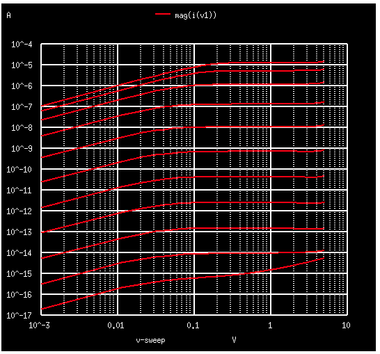
1)Sanity checking subthresshold behavior of NMOS.
2)DC sweep the gate voltage
3)Plot i(V1) loglog
4)Note lab data included at end of spice file.
=================================================================
NMOS_bsim3_SubSanity
* _______
* 3 _|_ _|_
* /V1 \ /Vds\
* \___/ \___/
* __| 1 |
* ||____ _|_
* 2 __|| | ///
* _|_ ||-> |
* /Vgs\ |_|
* \___/ _|_
* | ///
* _|_
* ///
*
Vds 3 0 dc 5v
Vgs 2 0 dc 1.2v
v1 3 1 dc 0v
m1 1 2 0 0 N1 W=3u L=1u AD=7p AS=7p PD=10u PS=10u
.OPTIONS GMIN=1e-15 METHOD=gear ABSTOL=1e-15
.dc Vds 1m 5 0.01 vgs 0 1 .1
.control
run
plot mag(i(v1)) loglog
.endc
***************SILICON_DATA****************************
* see reference curve below
*Lmin= .35 Lmax= 20 Wmin= .6 Wmax= 20
.model N1 NMOS
+ Level= 8 Tnom=27.0
*------------------Process-----------------------------------------------
+ tox=160e-10 xj=0.25e-06 nch=0.5e+17
*------------------V_threshold-------------------------------------------
+ vth0=0.72 nlx=0.12e-06
*------------------Bulk--------------------------------------------------
+ k1=1.04 k2=-1.209E-01
+ cdsc=-2.4E-4 cdscd=-1.506E-04 cdscb=-2.219E-04
*------------------mobility----------------------------------------------
+ u0=678 ua=8.964e-10
+ ub=1.472e-18 uc=-4.441E-17 vsat=86000
*------------------Subthresshold-----------------------------------------
+ nfactor=1.8
+ cit=-5.0E-04 voff=-7.862E-02
+ eta0=4.441e-16 etab=-2.E-01 dsub=0.7
*------------------Hot electrons-----------------------------------------
+ alpha0=1.61e-05 beta0=36.68
*------------------VAF---------------------------------------------------
+ lint=.12e-06 pclm=.19 pscbe1=3.79e+08 pscbe2=9.4e-05
+ delta=0.01655 pvag=0.4484
*------------------Bulk_diode--------------------------------------------
+ js=5.858e-08
*------------------Resistance--------------------------------------------
+ rsh=70 rdsw=375
+ wr=0.7586 prwb=0 prwg=-4.441E-17
*------------------Capacitance-------------------------------------------
+ cj=0.0002424 cjsw=2.73e-10 mj=0.3551 mjsw=0.3873
+ cgso=9e-13 cgdo=9e-13 cgbo=7e-10
+ pb=0.5614 pbsw=0.8 xpart=0
+ dlc=5e-08 dwc=1.5e-07
*------------------BulkChargeEffect--------------------------------------
+ a0=0.7 a1=0 a2=1 ags=0.05583
+ b0=6.305e-08 b1=6.579e-08 keta=-1.531E-02
*------------------ShortChannel------------------------------------------
+ dvt0=2.2 dvt1=0.53 dvt2=-1.521E-01 drout=0.76
+ pdiblcb=.4 pdiblc1=0.00886 pdiblc2=0.00029
*------------------NarrowChannel-----------------------------------------
+ w0=2.6e-04 wint=0.16e-06
+ ww=-9.525E-14 wwn=1.0
+ dvt0w=0 dvt1w=5.3e6 dvt2w=-1.E-01
+ k3=2.53 k3b=-5 dwg=0 dwb=0
*------------------Noise-------------------------------------------------
+ af=1 kf=1e-28 ef=0.95
*------------------Temperature-------------------------------------------
+ pvsat=0 ute=-1.258E+00 kt1=-3.85E-01
+ kt1l=0 kt2=-3.098E-02 ua1=5.705e-09
+ ub1=-1.147E-17 uc1=-1.302E-01 at=20380
* prt=-3.287E+02 lk1=0 lk2=0
+ lvsat=0 la0=0 lags=0 lute=0
+ luc=0
*Lmin= .35 Lmax= 20 Wmin= .6 Wmax= 20
.model N2 NMOS
+Level= 8 Tnom=27.0
****************Process***********************
+Tox=16e-9 Xj=250E-09 Nch=.5E+17
****************V_thresshold***********************
+Vth0=.72 Nlx=0.12E-06
****************Bulk***********************
+K1=1.04 K2=-1.2e-1 K3=-2.612
****************Mobility***********************
+U0=478 Ua=6.47e-9
+Ub=4.23e-18 Uc=-4.706281E-11 Vsat=86301
****************Subthresshold***********************
+NFactor=1.14
+Cit= 1.6E-04 Voff=-6.74E-02
+Eta0=1.03E-02 Etab=-5.04E-03 Dsub= .32
****************VAF***********************
+Lint=.12e-6 Pclm=.19 Pscbe1=4e8 Pscbe2=5E-09
+delta=0.01 Pvag=.44
****************Resistance***********************
+Rdsw=650 Prwg =0 Prwb = -.213 wr=1
****************Capacitance***********************
+Cdsc=-2.15E-05 Cdscb=0 Cdscd=0
****************BulkChargeEfffect***********************
+A0=.35 A1= 2.8E-02 A2= .9 Ags=.1
+B0=0.546 B1=1 Keta=-3.6E-02
****************ShortChannel***********************
+Dvt0=2.812 Dvt1= 0.462 Dvt2=-9.2e-2 Drout= .31871233
+Pdiblcb= -.234 Pdiblc1= 2.5E-03 Pdiblc2=6.4E-03
****************NarrowChannel***********************
+W0=1.163e-6 Wint=1.47e-7 Ww=-1.42E-09 Wwn=.2613948
+Wl=0 Wwl=0 Wln=0
+Dvt0w=0 Dvt1w=0 Dvt2w=0
+K3b= 2.233 Dwg=-6.0E-09 Dwb= -3.56E-09
****************Process***********************
+Ll=1.30E-10 Lw=0 Lwl=0
+Lln=.316394 Lwn=0
+Ute=-1.48
****************Temperature***********************
+Kt1l=0 kt1=-.3 kt2=-.051
+Ua1= 3.31E-10 Ub1= 2.61E-19 Uc1= -3.42e-10
+At= 22400 Prt=764.3
.model NMOSC NMOS
.model NMOSC NMOS
+ Level= 8 Tnom=27.0
*------------------Process-----------------------------------------------
+ tox=160e-10 xj=0.25e-06 nch=0.5e+17
*------------------V_threshold-------------------------------------------
+ vth0=0.72 nlx=0.12e-06
*------------------Bulk--------------------------------------------------
+ k1=1.04 k2=-1.209E-01
*------------------mobility----------------------------------------------
+ u0=678 ua=8.964e-10
+ ub=1.472e-18 uc=-4.441E-17 vsat=86000
*------------------Subthresshold-----------------------------------------
+ nfactor=1.8
+ cit=-5.0E-04 voff=-7.862E-02
+ eta0=4.441e-16 etab=-2.E-01 dsub=0.7
*------------------Hot electrons-----------------------------------------
* alpha0=1.61e-05 beta0=36.68
*------------------VAF---------------------------------------------------
+ lint=.12e-06 pclm=.19 pscbe1=3.79e+08 pscbe2=9.4e-05
+ delta=0.01655 pvag=0.4484
*------------------Bulk_diode--------------------------------------------
* + js=5.858e-08
*------------------Resistance--------------------------------------------
+ rsh=70 rdsw=375
+ wr=0.7586 prwb=0 prwg=-4.441E-17
*------------------Capacitance-------------------------------------------
+ cj=0.0002424 cjsw=2.73e-10 mj=0.3551 mjsw=0.3873
+ cgso=9e-13 cgdo=9e-13 cgbo=7e-10
+ cdsc=-2.4E-4 cdscd=-1.506E-01 cdscb=-2.219E-04
+ pb=0.5614 pbsw=0.8 xpart=0
+ dlc=5e-08 dwc=1.5e-07
*------------------BulkChargeEffect--------------------------------------
* a0=0.7 a1=0 a2=1 ags=0.05583
* b0=6.305e-08 b1=6.579e-08 keta=-1.531E-02
*------------------ShortChannel------------------------------------------
+ dvt0=2.2 dvt1=0.53 dvt2=-1.521E-01 drout=0.76
+ pdiblcb=.4 pdiblc1=0.00886 pdiblc2=0.00029
*------------------NarrowChannel-----------------------------------------
+ w0=2.6e-04 wint=0.16e-06
+ ww=-9.525E-14 wwn=1.0
+ dvt0w=0 dvt1w=5.3e6 dvt2w=-1.E-01
+ k3=2.53 k3b=-5 dwg=0 dwb=0
*------------------Noise-------------------------------------------------
* af=1 kf=1e-28 ef=0.95
*------------------Temperature-------------------------------------------
* pvsat=0 ute=-1.258E+00 kt1=-3.85E-01
* kt1l=0 kt2=-3.098E-02 ua1=5.705e-09
* ub1=-1.147E-17 uc1=-1.302E-01 at=20380
* prt=-3.287E+02 lk1=0 lk2=0
* lvsat=0 la0=0 lags=0 lute=0
* luc=0
.end
* source /Users/don_sauer/Downloads/SI_Lib/Tests.cir
***************SILICON_DATA*****************************
*
* NMOS_Subthresshold_Drain_Current and Gate_Voltage
* 1mA _______________________________________________
* | . . . .
* | w=20um . l = 1u . . .
* | . . . .
* 100uA |.......................................960mV....
* | . . 960mV .
* | . 960mV . 840mV .
* | . . 840mV .
* 10uA |.....................840mV......................
* | 960mV . . .
* | . . . 720mV .
* | 840mV 720mV 720mV .
* 1uA |................................................
* | . . . .
* |960mV 720mV . . .
* |840mV . . . 600mV .
* 100nA |.....................600mV......600mV...........
* | . . . .
* |720mV 600mV . . .
* | . . . 480mV .
* 10nA |................................480mV...........
* | . 480mV . .
* |600mV 480mV . . .
* | . . . .
* 1nA |.......................................360mV....
* | . . 360mV .
* | . 360mV . .
* | . . . .
* 100pA |480mV.....360mV........................240mV....
* | . . . .
* | . . 240mV .
* | . 240mV . .
* 10pA |360mV..................................120mV....
* | . . . .
* | 240mV . . .
* | . . . .
* 1pA |..240mV..............120mV......120mV...0mV.....
* | . . . .
* | 120mV . 0mV .
* | . . . .
* 100fA |__120mV__________________0mV___________________.
* 1mV 10mV 100mV 1V 10V
*
* Drain Voltage
=====================END_OF_SPICE=======================
==================Match_NPN_TC_to_Silicon======================
1)Sanity checking the temperature behavior of npnv
2)Do a foreach tempval
3)Set temp = $tempval each time
4)Simulate and measure for each temp simulation
5)echo Temp = $temp C_deg Vbe = $&vbe Beta = $&beta
6)Note the actual silicon data is included at end of spice file
=================================================================
Test Match NPN TC to Silicon
* _____
* | 0| Use this to simulate Vbe and Beta over temp.
* | _|_ Tweek the model terms IS, XTB, and XTI.
* | / _ \ Repeat until simulations match actual silicon.
* _|_ \/ \/ Different simulators often give different results!
* /// /\_/\ I1
* \___/ V2 R2
* | __/\ /\ /\__
* _______|_________ C _|_ \/ \/ _|_
* | |C ____ / \ ///
* | R1 _| |EGbas|
* |___/\ /\ /\_|' npn ____| |
* \/ \/ |`-> B \___/
* B | _|_
* _|_ ///
* ///
I1 0 C DC 1e-6
R1 C B 1
R2 V2 0 1k
Q1 C B 0 npnv 1
EGbas V2 0 C B 1
.control
foreach tempval -55 -35 -15 5 25 45 65 85 105 125
set temp = $tempval
op
let beta = mag(1e-6/v2)
let vbe = mag(b)
echo Temp = $temp C_deg Vbe = $&vbe Beta = $&beta
end
.endc
.model npnv npn (
*==========================================================
+IS=1.1E-17 NF=1.0 BF=120 VAF=30 IKF=6e-03
+ NR=1.0 BR=0.5 VAR=4 IKR=3e-04
+ISE=9E-17 NE=2
+ISC=1E-21 NC=2
+RB=750 RBM=450 IRB=8E-04
+RE=17 RC=110
*==========================================================
+CJE=2E-14 VJE=0.65 MJE=0.3
+CJC=2E-14 VJC=0.65 MJC=0.3
+CJS=3E-14 VJS=0.35 MJS=0.19 XCJC=0.42
+TF=2E-11 XTF=1.25 VTF=1 ITF=0.0035
+TR=6E-09 FC=0.9 PTF=210
*==========================================================
+KF=1.0E-16 AF=1
+XTB=1.4 EG=1.11 XTI=8 TNOM=25
.end
*********Actual Silicon DATA***********************
** Temp NPN_1uA Beta
** -55 8.23E-01 67%
** -35 7.87E-01
** -15 7.43E-01 75%
** 5 6.96E-01
** 25 6.53E-01 100%
** 45 6.09E-01
** 65 5.64E-01 125%
** 85 5.19E-01
** 105 4.74E-01
** 125 4.17E-01 160%
** tweek XTI & IS XTB
* source /Users/don_sauer/Downloads/SI_Lib/Tests.cir
=====================END_OF_SPICE=======================
temp = -55 c_deg vbe = 0.823219 beta = 62.3451
temp = -35 c_deg vbe = 0.782302 beta = 71.2528
temp = -15 c_deg vbe = 0.740177 beta = 80.6774
temp = 5 c_deg vbe = 0.696933 beta = 90.6232
temp = 25 c_deg vbe = 0.652636 beta = 101.095
temp = 45 c_deg vbe = 0.607372 beta = 112.1
temp = 65 c_deg vbe = 0.561192 beta = 123.644
temp = 85 c_deg vbe = 0.514146 beta = 135.734
temp = 105 c_deg vbe = 0.466281 beta = 148.378
temp = 125 c_deg vbe = 0.417638 beta = 161.583
==============X-Y Plot example (CDHW Version)=====================
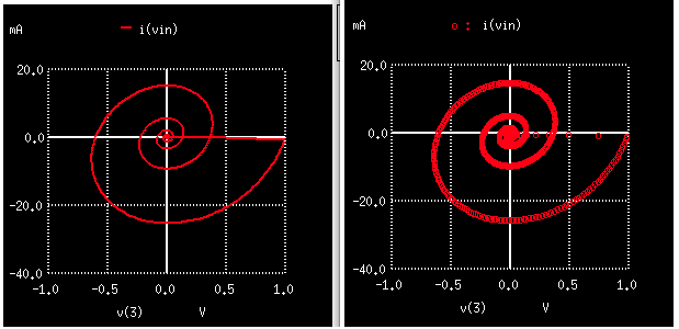
X-Y Plot example (CDHW Version)
vin 1 0 pulse 0 1 10u
r1 1 2 10
c1 2 3 1u
l1 3 0 1m
.control
tran 1u 1000u
plot v(3)
plot i(vin)
plot i(vin) vs v(3)
plot i(vin) vs v(3) pointplot
.endc
.end
=====================END_OF_SPICE=======================
===================RMS_Noise_Tests======================
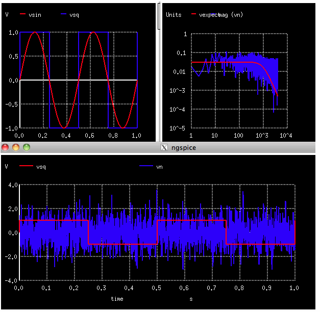
1)Create a Vsin sine wave and Vsq square wave having 1V peak magnitude
2)Create Vn TRNOISE noise wave having magnitude 1 and period 1/2 msec
3)The sqrt(mean(vsin*vsin)) will do an RMS of vsin
4)The RMS values for vsin is printed in $&RmsValsin format
5)The RMS values for vsin, Vsq and Vn are 0.707, 1, and 0.87
6)Sanity test the measure trans statements
7)The noise Vn should have a bandwidth of 1KHz for a 1/2msec sample rate
8)The total sample time is 1 sec for a 1Hz resolution
9)Set the spectrum bandwidth and resolution at 4KHz and 1Hz
10)The RMS of Vn should be spread over 1000 frequency bins
11)The average value of Vn over 1000 frequency bins should be 1/sqrt(1k)
12)The bandwidth of Vn should be 1KHz.
=================================================================
RMS_Tests
VT Vtime 0 PWL(0 0 1 1 )
Bsin Vsin 0 V = sin(6.283185307179586232*2*v(Vtime) )
Bsq Vsq 0 V = 2*u(V(Vsin)) -1
Vn Vn 0 TRNOISE( 1 .5m 0 0) $ 1Vrms, 0.5m period, 1/fslope=0, 1/fmag=0
.control
*destroy all
tran .5m 1
plot Vsin Vsq
plot Vsq Vn
let RmsValsin = sqrt(mean(vsin*vsin))
let RmsValsq = sqrt(mean(vsq*vsq))
let RmsValn = sqrt(mean(vn*vn))
echo "RMS level sin $&RmsValsin"
echo "RMS level sq $&RmsValsq"
echo "RMS level nois $&RmsValn"
meas tran vsin_rms RMS vsin from=0m to=1
meas tran vsq_rms RMS vsq from=0m to=1
meas tran vn_rms RMS vn from=0m to=1
let FFT_BandWidth_Hz = 4k
let FFT_resolution_Hz = 1
echo "FFT_BandWidth_Hz= $&FFT_BandWidth_Hz"
echo "FFT_resolution_Hz= $&FFT_resolution_Hz"
set specwindow= "rectangular"
spec $&FFT_resolution_Hz $&FFT_BandWidth_Hz $&FFT_resolution_Hz v(vn)
let Vexpect = 1/ (sqrt(1000)*(1+sqrt(frequency/1000)*sqrt(frequency/1000)*sqrt(frequency/1000)))
plot Vexpect mag(vn) loglog
let freq1 = frequency[100]
echo "Freq at index 100 = $&freq1"
*display
.endc
.end
* source /Users/don_sauer/Downloads/SI_Lib/Tests.cir
=====================END_OF_SPICE=======================
rms level sin 0.706959
rms level sq 0.999943
rms level nois 0.885789
vsin_rms = 7.07108e-01 from= 0.00000e+00 to= 1.00000e+00
vsq_rms = 9.99999e-01 from= 0.00000e+00 to= 1.00000e+00
vn_rms = 8.50116e-01 from= 0.00000e+00 to= 1.00000e+00
fft_bandwidth_hz= 4000
fft_resolution_hz= 1
freq at index 100 = 101
===============1_F_Tests=====================
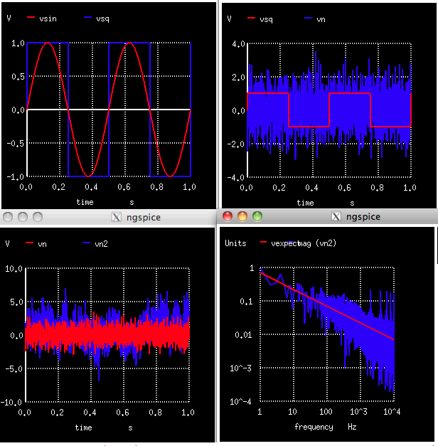
1)Create a Vsin sine wave and Vsq square wave and Vn noise wave at 1V peak magnitude
2)Create Vn TRNOISE noise wave having magnitude 1 and period 1/2 msec
2)Create Vn2 TRNOISE noise wave having two 1/f values of unity
3)The RMS values for vsin, Vsq, Vn and Vn2 are 0.707, 1, , 0.87, and 1.938
4)The noise Vn2 should have a bandwidth of 1KHz for a 1/2msec sample rate
5)The total sample time is 1 sec for a 1Hz resolution
6)Set the spectrum bandwidth and resolution at 4KHz and 1Hz
7)The spectrum for Vn2 is plotted with next to a 1/sqrt(frequency) reference
=================================================================
1_F_Tests
VT Vtime 0 PWL(0 0 1 1 )
Bsin Vsin 0 V = sin(6.283185307179586232*2*v(Vtime) )
Bsq Vsq 0 V = 2*u(V(Vsin)) -1
Vn Vn 0 TRNOISE( 1 .5m 0 0) $ 1Vrms, 0.05m period, 1/fslope=0, 1/fmag=0
Vn2 Vn2 0 TRNOISE( 1 .5m 1 1) $ 1Vrms, 0.05m period, 1/fslope=1, 1/fmag=1
.control
*destroy all
tran .05m 1
plot Vsin Vsq
plot Vsq Vn
plot Vn Vn2
let RmsValsin = sqrt(mean(vsin*vsin))
let RmsValsq = sqrt(mean(vsq*vsq))
let RmsValn = sqrt(mean(vn*vn))
let RmsValn2 = sqrt(mean(vn2*vn2))
echo "RMS level sin $&RmsValsin"
echo "RMS level sq $&RmsValsq"
echo "RMS level nois $&RmsValn"
echo "RMS level oneF $&RmsValn2"
let FFT_BandWidth_Hz = 10k
let FFT_resolution_Hz = 1
echo "FFT_BandWidth_Hz= $&FFT_BandWidth_Hz"
echo "FFT_resolution_Hz= $&FFT_resolution_Hz"
set specwindow= "rectangular"
spec $&FFT_resolution_Hz $&FFT_BandWidth_Hz $&FFT_resolution_Hz v(vn2)
let Vexpect = .7/( sqrt(frequency))
plot Vexpect mag (vn2) loglog
let freq1 = frequency[100]
echo "Freq at index 100 = $&freq1"
*display
.endc
.end
* source /Users/don_sauer/Downloads/SI_Lib/Tests.cir
=====================END_OF_SPICE=======================
No. of Data Rows : 26005
rms level sin 0.707039
rms level sq 0.999981
rms level nois 0.848564
rms level onef 1.93869
fft_bandwidth_hz= 10000
fft_resolution_hz= 1
freq at index 100 = 101
ngspice 25 ->

================CREATE/SAVE_PWL_WAVEFORM_THD=====================


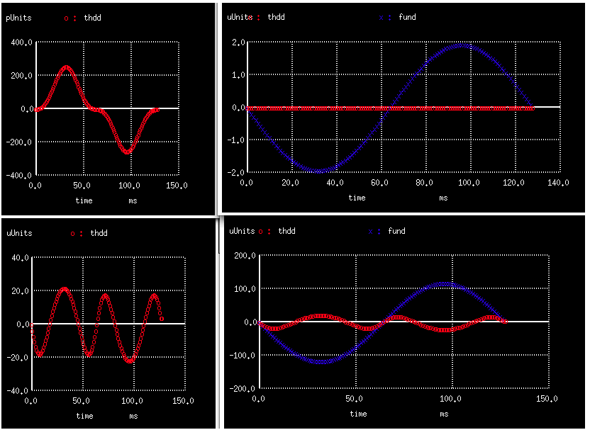
1)Create a DC voltage source V1 to receive array data into it’s PWL port
2)Create pwl_pars1 array using vector(2*129)*tstep*0.5
3)Install 129 point sine wave data points into pwl_pars1 in PWL format
4)Write pwl_pars1 to output file "~output.txt" for viewing
5)Install pwl_pars1 into V1 PWL’s port
6)Run transient for 128msec and linearize
7)Create a 129 point square wave squar
8)Multiply output V(1)by square wave squar and average to find magnitude magg
9)Subtract a perfect sinewave fund of magnitude magg from output V(1)
10)Plot this error signal thdd
11)RMS both fundamental fund and distortion thdd and find ration in percent format
12)Print both input_magnitude and THD_%
=================================================================
NON_FFT_THD_VIN
* ^ VC
* /_\
* |
* __/\ /\ /\_|__/\ /\ /\__
* | \/ \/ \/ \/ |
* | R1 R2 |
* VIN _|VCN1 VCN2 |_
* _____|'QN1 QN2`|__
* | |`->1X 1X<-'| |
* _|_ |VEN1 | |
* /V1 \ |____________________________| _|_
* \___/ _|_ VEN1 ///
* | / _ \1I
* _|_ \/ \/
* /// /\_/\
* \___/
* _|_
* ///
.OPTIONS GMIN=1e-15 METHOD=gear ABSTOL=1e-15 temp=27
*====== ====== ====== ====== ====== ====== ======
VCC VC 0 DC 10
V1 V1 0 0 dc
VMAG VMAG 0 DC 1m
BIN BIN 0 V= V(VMAG)*V(V1)
QN1 VCN1 BIN VEN1 NPN1 1.00
QN2 VCN2 0 VEN1 NPN1 1.00
I1 VEN1 0 100u
R1 VCN1 VC 1
R2 VCN2 VC 1
BOUT 1 0 V = V(VCN1)-V(VCN2)
.control
*================Want_129_1ms_steps=======
let n = 129
let tstep = 1ms
*================The_PWL_needs_258_points_.5ms_each=======
let pwl_pars1 = vector(2*n)*tstep*0.5
*================View_The_PWL_array=======
let ii= vector(2*129)
*plot pwl_pars1 vs ii
*================Create_PWL_array=======
let index = 0
repeat $&n
let pwl_pars1[ 2*index+1] =sin(2*3.1415926*index/128)
let index = index + 1
end
*================Write_PWL_array=======
set outfile = "/Users/don_sauer/Downloads/SI_Lib/output.txt"
let index = 0
repeat 255
let val = pwl_pars1[index]
echo "$&index $&val" >> $outfile
let index = index + 1
end
*================Install_the_PWL_arrays=======
alter @v1[pwl] = pwl_pars1
*================Run_and_Plot=======
tran 1ms 128m
linearize
*================Create_SquareWave=======
let squar = vector(129)
let index = 0
repeat 129
let squar[index] = 1
if (index >63 )
let squar[index] = -1
end
let index = index + 1
end
let FF = 1.0075
let magg = FF*3.1415926*mean( v(1)*squar)/2
*plot v(1) pointplot
*print magg
*================Create_Fundamental=======
let fund= vector( 129)
let index = 0
repeat 129
let fund[index] =magg*sin(2*3.1415926*index/128)
let index = index + 1
end
*================Subtract_Fundamental=======
let thdd = v(1) -fund
*================View=======
plot thdd pointplot
plot thdd fund pointplot
let RmsValfund = sqrt(mean(fund*fund))
let RmsValthdd = sqrt(mean(thdd*thdd))
let thdPC = 100*RmsValthdd/RmsValfund
let Vin = mean(VMAG)
echo "THD = $&thdPC % At Vmag = $&Vin"
.endc
.model NPN1 NPN( BF=2100 VAF=216 )
.model PNP1 PNP( BF=2100 VAF=21)
.end
* source /Users/don_sauer/Downloads/SI_Lib/Tests.cir
=====================END_OF_SPICE=======================
No. of Data Rows : 570
thd = 0.0105797 % at vmag = 0.001
thd = 16.7357 % at vmag = 0.1
=============ALTERNATIVE_THD_VS_VIN=============
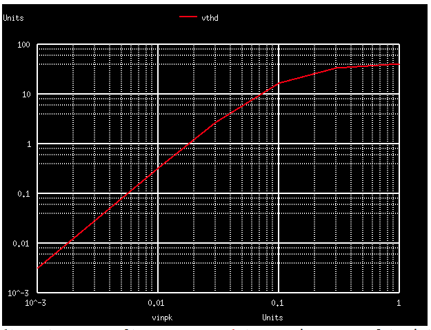
1)Create a DC voltage source V1 to receive array data into it’s PWL port
2)Create pwl_pars1 array using vector(2*129)*tstep*0.5
3)Install 129 point sine wave data points into pwl_pars1 in PWL format
4)Write pwl_pars1 to output file "~output.txt" for viewing
5)Install pwl_pars1 into V1 PWL’s port
6)Run transient for 128msec and linearize
7)Create a 129 point square wave squar
8)Multply output V(1)by square wave squar and average to find magnitude magg
9)Subtract a perfect sinewave fund of magnitude magg from output V(1)
10)Plot this error signal thdd
11)RMS both fundamental fund and distortion thdd and find ration in percent format
12)Print both input_magnitude and THD_%
13)Do foreach for VinMag at levels of 1m 10m 30m 100m 300m 1000m
14)Alter VMAG = $VinMag and transient simulate
15)Extract values from each run as tran2.fund etc
16)Use vector(6) to create two arrays Vthd and Vinpk
17)Plot Vthd vs Vinpk
18) Use destroy all to clear the plots
========================================================================
THD_VIN_magnitude
* ^ VC
* /_\
* |
* __/\ /\ /\_|__/\ /\ /\__
* | \/ \/ \/ \/ |
* | R1 R2 |
* VIN _|VCN1 VCN2 |_
* _____|'QN1 QN2`|__
* | |`->1X 1X<-'| |
* _|_ |VEN1 | |
* /VIN\ |____________________________| _|_
* \___/ _|_ VEN1 ///
* | / _ \1I
* _|_ \/ \/
* /// /\_/\
* \___/
* _|_
* ///
.OPTIONS GMIN=1e-15 METHOD=gear ABSTOL=1e-15 temp=27
*====== ====== ====== ====== ====== ====== ======
VCC VC 0 DC 10
V1 V1 0 0 dc
VMAG VMAG 0 DC 1m
BIN BIN 0 V= V(VMAG)*V(V1)
QN1 VCN1 BIN VEN1 NPN1 1.00
QN2 VCN2 0 VEN1 NPN1 1.00
I1 VEN1 0 100u
R1 VCN1 VC 1
R2 VCN2 VC 1
BOUT 1 0 V = V(VCN1)-V(VCN2)
.control
destroy all
*===============Want_129_1ms_steps=======
let n = 129
let tstep = 1ms
*===============The_PWL_needs_258_points_.5ms_each=======
let pwl_pars1 = vector(2*n)*tstep*0.5
*===============View_The_PWL_array=======
let ii= vector(2*129)
*plot pwl_pars1 vs ii
*===============Create_PWL_array=======
let index = 0
repeat $&n
let pwl_pars1[2*index+1] =sin(2*3.1415926*index/128)
let index = index + 1
end
*===============Write_PWL_array=======
set outfile = "/Users/don_sauer/Downloads/SI_Lib/OpAmpCornerData.txt"
let index = 0
repeat 255
let val = pwl_pars1[index]
echo "$&index $&val" >> $outfile
let index = index + 1
end
*===============Install_the_PWL_arrays=======
alter @v1[pwl] = pwl_pars1
*===============Loop_VIN=======
foreach VinMag 1m 10m 30m 100m 300m 1000m
alter VMAG = $VinMag
*===============Run_and_Plot=======
tran 1ms 128m
linearize
*===============Create_SquareWave=======
let squar= vector(128)
let index = 0
repeat 129
let squar[index] = 1
if (index >63 )
let squar[index] = -1
end
let index = index + 1
end
let FF = 1.008
let magg = FF*3.1415926*mean( v(1)*squar)/2
*plot v(1) pointplot
*print magg
*===============Create_Fundamental=======
let fund= vector(129)
let index = 0
repeat 129
let fund[index] =magg*sin(2*3.1415926*index/128)
let index = index + 1
end
*===============Subtract_Fundamental=======
let thdd = v(1) -fund
*===============View=======
*plot thdd pointplot
*plot thdd fund pointplot
let RmsValfund = sqrt(mean(fund*fund))
let RmsValthdd = sqrt(mean(thdd*thdd))
let thdPC = 100*RmsValthdd/RmsValfund
let Vin = mean(VMAG)
echo "THD = $&thdPC % At Vmag = $&Vin"
end
echo $plots
*set plot tran3
*plot tran2.thdd
*plot tran4.thdd
*plot tran2.fund
*plot tran4.fund
let Vthd = vector(6)
let Vinpk= vector(6)
let RmsValfund = sqrt(mean(tran2.fund*tran2.fund))
let RmsValthdd = sqrt(mean(tran2.thdd*tran2.thdd))
let Vthd[0] = 100*RmsValthdd/RmsValfund
let Vinpk[0] = 1m
let RmsValfund = sqrt(mean(tran4.fund*tran4.fund))
let RmsValthdd = sqrt(mean(tran4.thdd*tran4.thdd))
let Vthd[1] = 100*RmsValthdd/RmsValfund
let Vinpk[1] = 10m
let RmsValfund = sqrt(mean(tran6.fund*tran6.fund))
let RmsValthdd = sqrt(mean(tran6.thdd*tran6.thdd))
let Vthd[2] = 100*RmsValthdd/RmsValfund
let Vinpk[2] = 30m
let RmsValfund = sqrt(mean(tran8.fund*tran8.fund))
let RmsValthdd = sqrt(mean(tran8.thdd*tran8.thdd))
let Vthd[3] = 100*RmsValthdd/RmsValfund
let Vinpk[3] = 100m
let RmsValfund = sqrt(mean(tran10.fund*tran10.fund))
let RmsValthdd = sqrt(mean(tran10.thdd*tran10.thdd))
let Vthd[4] = 100*RmsValthdd/RmsValfund
let Vinpk[4] = 300m
let RmsValfund = sqrt(mean(tran12.fund*tran12.fund))
let RmsValthdd = sqrt(mean(tran12.thdd*tran12.thdd))
let Vthd[5] = 100*RmsValthdd/RmsValfund
let Vinpk[5] = 1000m
plot Vthd vs Vinpk loglog
.endc
.model NPN1 NPN( BF=2100 VAF=216 )
.model PNP1 PNP( BF=2100 VAF=21)
.end
* source /Users/don_sauer/Downloads/SI_Lib/Tests.cir
=====================END_OF_SPICE=======================
thd = 0.00314473 % at vmag = 0.001
thd = 0.324393 % at vmag = 0.01
thd = 2.70768 % at vmag = 0.03
thd = 16.7873 % at vmag = 0.1
thd = 33.3636 % at vmag = 0.3
thd = 40.4533 % at vmag = 1
const tran1 tran2 tran3 tran4 tran5 tran6 tran7 tran8 tran9 tran10 tran11 tran12
ngspice 23 ->
==============Reshape_A_Vector======================
1)The vector(9) statement creates an array from 0 to nine
2)The reshape newvec [ 1 ] [ 3 ] translate it to a 3X3 array
=================================================================
Reshape_A_Vector
.control
let newvec= vector( 9 ) $ generate vector with all (here9) elements
print newvec
reshape newvec [ 1 ] [ 3 ] $ reshapevectortoformat 1 x 3
print newvec [ 0 ] [ 3 ] $ access elements of the reshaped vector
print newvec [ 1 ] [ 3 ]
let newt = newvec [ 2 ] [ 3 ] $ copy vector
print newt
.endc
.end
* /usr/local/bin/ngspice
* source /Users/don_sauer/Downloads/SI_Lib/vectRshape.cir
* run
* source /Users/don_sauer/Downloads/SI_Lib/vectRshape.cir
=====================END_OF_SPICE=======================
Circuit: vectrshape
--------------------------------------------------------------------------------
Index newvec
--------------------------------------------------------------------------------
0 0.000000e+00
1 1.000000e+00
2 2.000000e+00
3 3.000000e+00
4 4.000000e+00
5 5.000000e+00
6 6.000000e+00
7 7.000000e+00
8 8.000000e+00
--------------------------------------------------------------------------------
Index newvec [ 0 ] [
--------------------------------------------------------------------------------
0 0.000000e+00
1 1.000000e+00
2 2.000000e+00
--------------------------------------------------------------------------------
Index newvec [ 1 ] [
--------------------------------------------------------------------------------
0 3.000000e+00
1 4.000000e+00
2 5.000000e+00
--------------------------------------------------------------------------------
Index newt
--------------------------------------------------------------------------------
0 6.000000e+00
1 7.000000e+00
2 8.000000e+00
ngspice 3 ->
===============Control_structure_Examples==============
1)Control structure templates
2)Include dowhile, while, repeat, break, foreach, if, else, and goto
=================================================================
Control_structure_Examples
* vectors are used ( except foreach )
* start in interactive mode
.control
* test sequence for while , dowhile
let loop = 0
echo
echo enter loop with "$&loop "
dowhile loop < 3
echo within dowhile loop "$&loop "
let loop = loop + 1
end
echo after dowhile loop "$&loop "
* enter loop with 0
* within dowhile loop 0
* within dowhile loop 1
* within dowhile loop 2
* after dowhile loop 3
echo
let loop = 0
while loop < 3
echo within while loop "$&loop "
let loop = loop + 1
end
echo after while loop "$&loop "
* within while loop 0
* within while loop 1
* within while loop 2
* after while loop 3
* test for while , repeat , if , break
let loop = 0
while loop < 4
let index = 0
repeat
let index = index + 1
if index > 4
break
end
end
echo index "$&index " loop "$&loop "
let loop = loop + 1
end
* index 5 loop 0
* index 5 loop 1
* index 5 loop 2
* index 5 loop 3
* test sequence for foreach
echo
foreach outvar 0 0.5 1 1.5
echo parameters : $outvar $ foreach parameters are variables , $ not vectors !
end
* parameters : 0
* parameters : 0.5
* parameters : 1
* parameters : 1.5
* test for if ... else ... end
echo
let loop = 0
let index = 1
dowhile loop < 10
let index = index * 2
if index < 128
echo "$&index " lt 128
else
echo "$&index " ge 128
end
let loop = loop + 1
end
* 2 lt 128
* 4 lt 128
* 8 lt 128
* 16 lt 128
* 32 lt 128
* 64 lt 128
* 128 ge 128
* 256 ge 128
* 512 ge 128
* 1024 ge 128
* simple test for label , goto
echo
let loop = 0
label starthere
echo start "$&loop "
let loop = loop + 1
if loop < 3
goto starthere
end
echo end "$&loop "
* start 0
* start 1
* start 2
* end 3
* test for label , nested goto
echo
let loop = 0
label starthere1
echo start nested "$&loop "
let loop = loop + 1
if loop < 3
if loop < 3
goto starthere1
end
end
echo end "$&loop "
* start nested 0
* start nested 1
* start nested 2
* end 3
* test for label , goto
echo
let index = 0
label starthere2
let loop = 0
echo We are at start with index "$&index " and loop "$&loop "
if index < 6
label inhere
let index = index + 1
if loop < 3
let loop = loop + 1
if index > 1
echo jump2
goto starthere2
end
end
echo jump
goto inhere
end
echo We are at end with index "$&index " and loop "$&loop "
we are at start with index 0 and loop 0
* jump
* jump2
* we are at start with index 2 and loop 0
* jump2
* we are at start with index 3 and loop 0
* jump2
* we are at start with index 4 and loop 0
* jump2
* we are at start with index 5 and loop 0
* jump2
* we are at start with index 6 and loop 0
* we are at end with index 6 and loop 0
* jump
* test goto in while loop
let loop = 0
if 1 $ outer loop to allow nested forward label ’endlabel ’
while loop < 10
if loop > 5
echo jump
goto endlabel
end
let loop = loop + 1
end
echo before $ never reached
label endlabel
echo after "$&loop "
end
* after 6
* test for using variables , simple test for label , goto
set loop = 0
label starthe
echo start $loop
let loop = $loop + 1 $ expression needs vector at lhs
set loop = "$&loop" $ convert vector contents to variable
if $loop < 3
goto starthe
end
echo end $loop
* start 0
* start 1
* start 2
* end 3
.endc
.end
* /usr/local/bin/ngspice
* source /Users/don_sauer/Downloads/SI_Lib/Control_structure.cir
=====================END_OF_SPICE=======================
==============Gaussian_Histogram===================
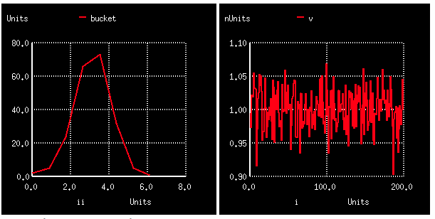
1)Define a function aguass
2)Create an univec array called bucket
3)Compose vectors i and v
4)Use a Dowhile 200 times on aguass
5)Transfer value of aguass to v
6)Add to bucket if value of aguass within limits
7)prints and plots bucket and v vs i
===============================================
Gaussian_Histogram
.control
define agauss (nom, avar , sig ) ( nom + avar/sig*sgauss ( 0 ) )
let mc_runs = 200
let run = 0
let no_buck = 8
let bucket = unitvec( no_buck )
let delta = 3e-11
let lolimit = 1e-09 - 3*delta
let hilimit = 1e-09 + 3*delta
compose i start = 0 stop = 200 step =1
compose v start = 0 stop = 200 step =1
let j = 0
dowhile run < mc_runs
let val = agauss(1e-09, 1e-10 , 3)
let v[ j ] = val
let j = j +1
if (val < lolimit )
let bucket [ 0 ] = bucket[ 0 ] + 1
end
let v[200] = 1n
let part = 1
dowhile part < ( no_buck - 1)
if ((val < ( lolimit + part*delta ) ) & ( val > ( lolimit + ( part -1)*delta) ) )
let bucket[ part ] = bucket[ part ] + 1
break
end
let part = part + 1
end
if (val > hilimit )
let bucket [ no_buck -1] = bucket [ no_buck -1] + 1
end
let run = run + 1
end
let part = 0
dowhile part < no_buck
let value = bucket[ part ] - 1
set value = "$&value"
echo $value
let part = part + 1
end
compose ii start = 0 stop = 7 step =1
plot bucket vs ii
plot v vs i
.endc
.end
* source /Users/don_sauer/Downloads/SI_Lib/Tests.cir
=====================END_OF_SPICE=======================
Circuit: test_gaussian
0
5
32
72
61
23
4
3
==============Testing_S_transfer_functions============
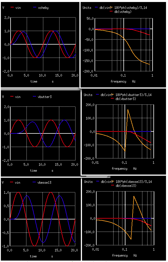
1)Normalize s to 1 rad/sec which is 0.159Hz.
2)Create 2pole cheby1 lowpass filter using 1 s_xfer on the poles and zeros
3)Create 6pole Bessel and butterworth using 3 s_xfer in series
4)Plot transient
5)Plot AC magnitude and phase in degrees format
===============================================
Testing_S_transfer_functions
vin vin 0 0.0 ac 1.0 sin(0 1 .1 )
acheby1 vin vcheby cheby1
abutter1 vin vbutter1 butter1
abutter2 vbutter1 vbutter2 butter2
abutter2 vbutter2 vbutter3 butter3
abessel1 vin vbessel1 bessel1
abessel2 vbessel1 vbessel2 bessel2
abessel2 vbessel2 vbessel3 bessel3
.model cheby1 s_xfer(num_coeff=[1] den_coeff=[1 1.09773 1.10251] int_ic=[0 0 0] denormalized_freq=1)
.model butter1 s_xfer(num_coeff=[1] den_coeff=[1 0.5176 1] int_ic=[0 0 0] denormalized_freq=1)
.model butter2 s_xfer(num_coeff=[1] den_coeff=[1 1.4142 1] int_ic=[0 0 0] denormalized_freq=1)
.model butter3 s_xfer(num_coeff=[1] den_coeff=[1 1.9319 1] int_ic=[0 0 0] denormalized_freq=1)
.model bessel1 s_xfer(num_coeff=[1] den_coeff=[1 1.861 3.63] int_ic=[0 0 0] denormalized_freq=1)
.model bessel2 s_xfer(num_coeff=[1] den_coeff=[1 2.76 2.85] int_ic=[0 0 0] denormalized_freq=1)
.model bessel3 s_xfer(num_coeff=[26.6] den_coeff=[1 3.143 2.57] int_ic=[0 0 0] denormalized_freq=1)
.control
tran 10e-3 20
plot vin vcheby
plot vin vbutter3
plot vin vbessel3
ac dec 10 .01 .9
plot db(vcheby) db(vin) 180*ph(vcheby)/3.14
plot db(vbutter3) db(vin) 180*ph(vbutter3)/3.14
plot db(vbessel3) db(vin) 180*ph(vbessel3)/3.14
.endc
.end
* source /Users/don_sauer/Downloads/SI_Lib/Tests.cir
=====================END_OF_SPICE=======================
=======================Testing_Fourier================================
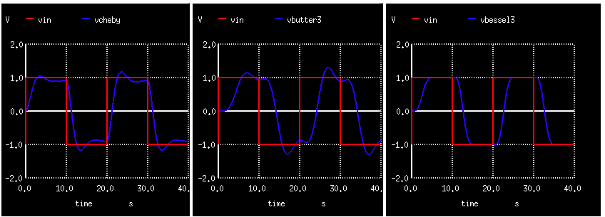
1)Normalize to 1 rad/sec which is 0.159Hz.
2)Create 2pole cheby1 lowpass filter using 1 s_xfer on the poles and zeros
3)Create 6pole Bessel and butterworth using 3 s_xfer in series
4)Create 1/20 Hz vin input
5)Plot transient inputs and outputs
6)Apply the fourier function to vin and vbutter1
7)Auto printout of harmonics
8)Should have access to fourier11 array?
===================================================
Testing_Fourier
vin vin 0 0.0 pulse(-1 1 100u 100u 100u 10 20 ) ac = 1
acheby1 vin vcheby cheby1
abutter1 vin vbutter1 butter1
abutter2 vbutter1 vbutter2 butter2
abutter2 vbutter2 vbutter3 butter3
abessel1 vin vbessel1 bessel1
abessel2 vbessel1 vbessel2 bessel2
abessel2 vbessel2 vbessel3 bessel3
.model cheby1 s_xfer(num_coeff=[1] den_coeff=[1 1.09773 1.10251] int_ic=[0 0 0] denormalized_freq=1)
.model butter1 s_xfer(num_coeff=[1] den_coeff=[1 0.5176 1] int_ic=[0 0 0] denormalized_freq=1)
.model butter2 s_xfer(num_coeff=[1] den_coeff=[1 1.4142 1] int_ic=[0 0 0] denormalized_freq=1)
.model butter3 s_xfer(num_coeff=[1] den_coeff=[1 1.9319 1] int_ic=[0 0 0] denormalized_freq=1)
.model bessel1 s_xfer(num_coeff=[1] den_coeff=[1 1.861 3.63] int_ic=[0 0 0] denormalized_freq=1)
.model bessel2 s_xfer(num_coeff=[1] den_coeff=[1 2.76 2.85] int_ic=[0 0 0] denormalized_freq=1)
.model bessel3 s_xfer(num_coeff=[26.6] den_coeff=[1 3.143 2.57] int_ic=[0 0 0] denormalized_freq=1)
.control
destroy all
tran 10e-3 40
plot vin vcheby
plot vin vbutter3
plot vin vbessel3
save all
fourier .05 vin
fourier .05 vbutter1
print fourier11 [1][1]
echo $plots
display
plot all
.endc
.end
* source /Users/don_sauer/Downloads/SI_Lib/Tests.cir
=====================END_OF_SPICE=======================
Fourier analysis for vin:
No. Harmonics: 10, THD: 42.9161 %, Gridsize: 200, Interpolation Degree: 1
Harmonic Frequency Magnitude Phase Norm. Mag Norm. Phase
-------- --------- --------- ----- --------- -----------
0 0 0 0 0 0
1 0.05 1.27329 -0.9 1 0
2 0.1 1.7109e-16 72.5351 1.34368e-16 73.4351
3 0.15 0.42457 -2.7 0.333443 -1.8
4 0.2 2.74176e-16 -119.47 2.15329e-16 -118.57
5 0.25 0.25491 -4.5 0.200198 -3.6
6 0.3 2.24161e-16 19.9831 1.76048e-16 20.8831
7 0.35 0.182258 -6.3 0.14314 -5.4
8 0.4 2.03946e-16 23.0757 1.60172e-16 23.9757
9 0.45 0.141943 -8.1 0.111478 -7.2
Fourier analysis for vbutter1:
No. Harmonics: 10, THD: 61.9513 %, Gridsize: 200, Interpolation Degree: 1
Harmonic Frequency Magnitude Phase Norm. Mag Norm. Phase
-------- --------- --------- ----- --------- -----------
0 0 2.35213e-05 0 0 0
1 0.05 1.38962 -10.137 1 0
2 0.1 0.000599338 147.022 0.000431296 157.16
3 0.15 0.845978 -76.584 0.608784 -66.447
4 0.2 0.00094568 48.8055 0.000680532 58.9428
5 0.25 0.151707 -150.49 0.109171 -140.35
6 0.3 0.000451974 24.1485 0.00032525 34.2858
7 0.35 0.0452444 -162.86 0.0325588 -152.72
8 0.4 0.000301101 19.2886 0.000216678 29.4259
9 0.45 0.0196028 -167.46 0.0141066 -157.32
Error(parse.c--checkvalid): fourier11: no such vector.
const tran1
Here are the vectors currently active:
Title: test_fourier
Name: tran1 (Transient Analysis)
Date: Tue Apr 9 13:30:18 2013
abessel1#branch_1_0 : current, real, 4126 long
abessel2#branch_1_0 : current, real, 4126 long
abessel2#branch_1_0 : current, real, 4126 long
abutter1#branch_1_0 : current, real, 4126 long
abutter2#branch_1_0 : current, real, 4126 long
abutter2#branch_1_0 : current, real, 4126 long
acheby1#branch_1_0 : current, real, 4126 long
time : time, real, 4126 long [default scale]
vbessel1 : voltage, real, 4126 long
vbessel2 : voltage, real, 4126 long
vbessel3 : voltage, real, 4126 long
vbutter1 : voltage, real, 4126 long
vbutter2 : voltage, real, 4126 long
vbutter3 : voltage, real, 4126 long
vcheby : voltage, real, 4126 long
vin : voltage, real, 4126 long
vin#branch : current, real, 4126 long
===================View_Phase_Distortion================================
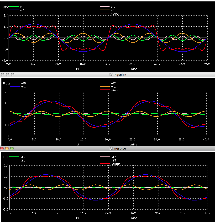
1)Normalize to 1 rad/sec which is 0.159Hz.
2)Create 2pole cheby1 lowpass filter using 1 s_xfer on the poles and zeros
3)Create 6pole Bessel and butterworth using 3 s_xfer in series
4)Create 1/20 Hz vin input
5)Plot transient inputs and outputs
6)The total sample time is 40sec for a resolution of 25m
7)The fundamento is at 20secs
8)The transient is run at 10msec for a nyquist at 50Hz
9)Find the spectrum of the output for the vin, vcheby1, vbessel3, and vbutter3 filters
10)Extract the fundamental and harmonics and plot on same graph
11)Notice how the input Vin and Vbessel have all the zero crossings lined up.
12)Notice how all the zero crossings don’t line up for Vbutter output
13)Phase distortion appears as output waveform shape distortion
===================================================
View_6Pole_Phase_Distortion
vin vinn 0 0.0 pulse(-1 1 100u 100u 100u 10 20 ) ac = 1
acheby1 vinn vcheby cheby1
abutter1 vinn vbutter1 butter1
abutter2 vbutter1 vbutter2 butter2
abutter2 vbutter2 vbutter3 butter3
abessel1 vinn vbessel1 bessel1
abessel2 vbessel1 vbessel2 bessel2
abessel2 vbessel2 vbessel3 bessel3
.model cheby1 s_xfer(num_coeff=[1] den_coeff=[1 1.09773 1.10251] int_ic=[0 0 0] denormalized_freq=1)
.model butter1 s_xfer(num_coeff=[1] den_coeff=[1 0.5176 1] int_ic=[0 0 0] denormalized_freq=1)
.model butter2 s_xfer(num_coeff=[1] den_coeff=[1 1.4142 1] int_ic=[0 0 0] denormalized_freq=1)
.model butter3 s_xfer(num_coeff=[1] den_coeff=[1 1.9319 1] int_ic=[0 0 0] denormalized_freq=1)
.model bessel1 s_xfer(num_coeff=[1] den_coeff=[1 1.861 3.63] int_ic=[0 0 0] denormalized_freq=1)
.model bessel2 s_xfer(num_coeff=[1] den_coeff=[1 2.76 2.85] int_ic=[0 0 0] denormalized_freq=1)
.model bessel3 s_xfer(num_coeff=[26.6] den_coeff=[1 3.143 2.57] int_ic=[0 0 0] denormalized_freq=1)
.control
*destroy all
tran 10e-3 40
plot vinn vcheby
plot vinn vbutter3
plot vinn vbessel3
let vin = vbessel3
*let vin = vinn
*let vin = vbutter3
let FFT_BandWidth_Hz = 50
let FFT_resolution_Hz = 25m
echo "FFT_BandWidth_Hz = $&FFT_BandWidth_Hz"
echo "FFT_resolution_Hz = $&FFT_resolution_Hz"
set specwindow = "rectangular"
spec $&FFT_resolution_Hz $&FFT_BandWidth_Hz $&FFT_resolution_Hz v(vin)
let Vexpect = (1/sqrt(1k))/(1+(frequency/1k)*(frequency/1k)*(frequency/1k))
plot Vexpect db(vin) 180*ph(vin)/3.14 xlog xlimit .01 1
let freq1 = frequency[1]
echo "Freq at index 1 = $&freq1"
echo $plots
display
let tt =vector(128)
let cos1=vector(128)
let sin1=vector(128)
let cos3=vector(128)
let sin3=vector(128)
let cos5=vector(128)
let sin5=vector(128)
let cos7=vector(128)
let sin7=vector(128)
let cos9=vector(128)
let sin9=vector(128)
let index = 0
repeat 128
let tt[index] = index*40/128
let cos1[index] = real(vin[1])*cos(2*3.141*index*2/128)
let sin1[index] = imag(vin[1])*sin(2*3.141*index*2/128)
let cos3[index] = real(vin[5])*cos(2*3.141*index*2*3/128)
let sin3[index] = imag(vin[5])*sin(2*3.141*index*2*3/128)
let cos5[index] = real(vin[9])*cos(2*3.141*index*2*5/128)
let sin5[index] = imag(vin[9])*sin(2*3.141*index*2*5/128)
let cos7[index] = real(vin[13])*cos(2*3.141*index*2*7/128)
let sin7[index] = imag(vin[13])*sin(2*3.141*index*2*7/128)
let cos9[index] = real(vin[17])*cos(2*3.141*index*2*9/128)
let sin9[index] = imag(vin[17])*sin(2*3.141*index*2*9/128)
let index =index +1
end
let vf1 = cos1+sin1
let vf3 = cos3+sin3
let vf5 = cos5+sin5
let vf7 = cos7+sin7
let vf9 = cos9+sin9
let vinput = cos1+sin1+cos3+sin3+cos5+sin5+cos7 +sin7 +cos9 +sin9
plot vinput vf1 vf3 vf5 vf7 vs tt
.endc
.end
* source /Users/don_sauer/Downloads/SI_Lib/Tests.cir
=====================END_OF_SPICE=======================
===================Analog_Models========================================
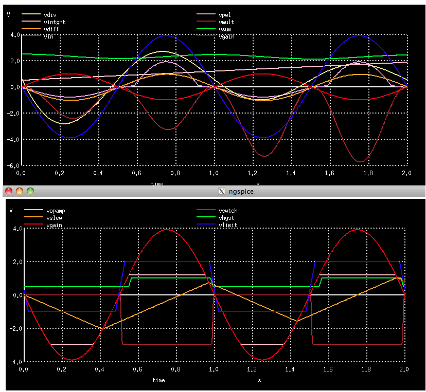
1)The signals are all Analog and floating and continuous
2)The math functions of add, multiply, and divide are included
2)The calculus functions of derivative, and integral are included
3)The limiting functions like limit and slew simplify modeling real devices
4)The piece wise linear nonlinearity and asymmetrical switching are available
=====================================================
Analog_Models
vin vin 0 0.0 ac 1.0 sin(0 1 1 )
Vcc Vcc 0 DC 5
Vee Vee 0 DC -3
again vin vgain gain_block
adiff vsum vdiff slope_gen
asum [vin vdiff] vsum sum1
aintgrt vsum vintgrt time_count
amult [vin vgain vintgrt] vmult sigmult
adiv vgain vintgrt vdiv divider
alimit vgain vlimit limit5
aslew vgain vslew slew1
ahyst vgain Vhyst schmitt1
aOPAmplim vgain Vcc Vee Vopamp amp3
rzout4 Vopamp 0 1200
aswtch vgain ( Vee vswtch) switch3
rzout3 vswtch 0 3.9k
apwlcntl vgain Vpwl xfer_cntl1
a8 %vd([1 0 2 0]) filesrc
.model gain_block gain ( gain = -3.9 out_offset = 7.003m )
.model slope_gen d_dt( out_offset=0.0 gain=1.0 out_lower_limit=-3 out_upper_limit=1e12 limit_range=1e-9)
.model sum1 summer ( in_offset =[0.1 -0.2] in_gain =[1.0 1.0] out_gain =5.0 out_offset = 3)
.model time_count int( in_offset=0.0 gain=.3 out_lower_limit=-1e12 out_upper_limit=1e12 limit_range=1e-9 out_ic=0.5)
.model sigmult mult ( in_offset =[0.1 0.1 -0.1] in_gain =[1.0 1.0 1.0] out_gain =1.0 out_offset =0.05)
.model divider divide( num_offset=0.1 num_gain=2.5 den_offset=-0.1 den_gain=5.0 den_lower.limit=1e-5 den_domain=1e-6
+ fraction=FALSE out_gain=1.0 out_offset=0.5)
.model limit5 limit( in_offset=0.1 gain=2.5 out_lower_limit=-1.0 out_upper_limit=2.0 limit_range=0.10 fraction=FALSE)
.model slew1 slew( rise_slope=0.5e1 fall_slope=0.5e1)
.model schmitt1 hyst( in_low=0.7 in_high=1.0 hyst=0.5 out_lower_limit=0.5 out_upper_limit=1.0 input_domain=0.01 fraction=TRUE)
.model amp3 ilimit( in_offset=0.0 gain=1.0 r_out_source=1.0 r_out_sink=1.0 i_limit_source=1e-3
+ i_limit_sink=10e-3 v_pwr_range=0.2 i_source_range=1e-3 i_sink_range=1e-3 r_out_domain=1e-3)
.model switch3 aswitch( cntl_off=0.0 cntl_on=.5 r_off=1e6 r_on=10.0 log=TRUE)
.model xfer_cntl1 pwl( x_array=[-2.0 -1.0 2.0 4.0 5.0]
+ y_array=[-0.4 -0.2 0.1 2.0 10.0]
+ input_domain=0.05 fraction=TRUE)
.model filesrc filesource (file="/Users/don_sauer/Downloads/SI_Lib/sine.m" amploffset=[0 0] amplscale=[1 1]
+ timeoffset=0 timescale=1 timerelative=false amplstep=false)
.control
destroy all
tran 1e-3 2
plot vin vgain vdiff vsum vintgrt vmult vdiv Vpwl
plot vgain vlimit vslew Vhyst Vopamp vswtch
plot v(1)
plot v(2)
.endc
.end
* source /Users/don_sauer/Downloads/SI_Lib/Tests.cir
=====================END_OF_SPICE=======================
Error: no such vector v(1)
Error: no such vector v(2)
================Testing_Digital_and_Real_Signal======================
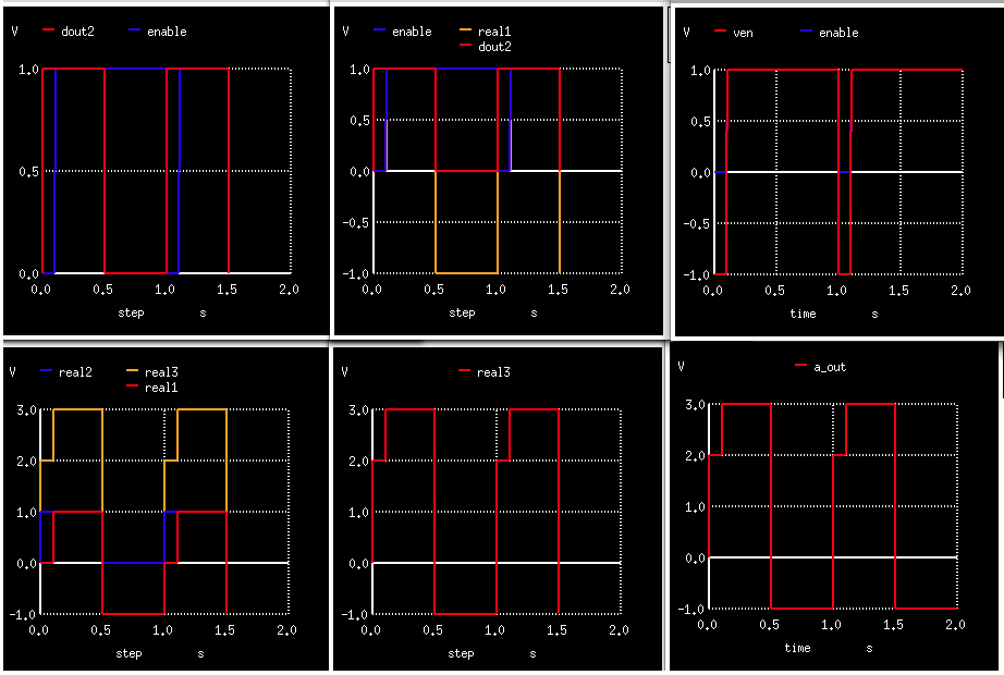
1)The signals vin and ven are Analog and floating and continuous
2)The adc_bridge converts vin into dout which is a Digital, binary,event driven signal
3)The dac_bridge converts dout into aout which is Analog and floating and continuos
4)The d_to_real converts dout2 into real1 which is Real and is floating event driven
5)Reals signal real1 and real2 can be gained by real_gain and summed together at real3
6)The pointplot option shows how the waveforms are stored and why translation is needed.
=====================================================
Testing_Digital_Real_Signal
vin vin 0 0.0 PULSE(-1 1 1m 1m 1m .5 1 )
ven ven 0 0.0 PULSE(-1 1 .1 1m 1m .9 1 )
*Vcc Vcc 0 DC 5
*Vee Vee 0 DC -5
aadc [vin] [dout] adc_buff
adac [dout] [aout] dac_buff
aadc2 [vin] [dout2] adc_buff2
aadc3 [ven] [enable] adc_buff3
a2real1 dout2 enable real1 node_bridge2
a2real2 dout2 dout2 real2 node_bridge2
abridge3 real3 a_out node_bridge3
an0a real1 real3 n0
az0a real2 real3 n1
.model adc_buff adc_bridge(in_low = 0.3 in_high = 3.5 rise_delay=.1 fall_delay=.1)
.model dac_buff dac_bridge(out_low = 0.0 out_high = 1.5 t_rise=.05 t_fall=.1)
.model adc_buff2 adc_bridge()
.model adc_buff3 adc_bridge()
.model node_bridge2 d_to_real (zero=-1 one=1 delay =.1p) $ digital to real with enable in,en,out
.model n0 real_gain (gain=1.0) $ gain block for event-driven real data in,out
.model n1 real_gain (gain=2.0)
.model node_bridge3 real_to_v $ gain block for event-driven real data in,out
.control
destroy all
tran 1e-3 2
*plot all
plot dout aout dout2
plot dout2 enable
plot ven enable
plot dout2 enable real1
plot real1 real2 real3
plot real3
plot a_out
display
.endc
.end
* source /Users/don_sauer/Downloads/SI_Lib/Tests.cir
=====================END_OF_SPICE=======================
Parameter_Name: t_rise t_fall
plot dout aout dout2 pointplot
plot dout2 enable pointplot
plot ven enable pointplot
plot dout2 enable real1 pointplot
plot real1 real2 real3 pointplot
plot real3 pointplot
plot a_out pointplot
========Counter_Translates_between_Real_and_Digital============
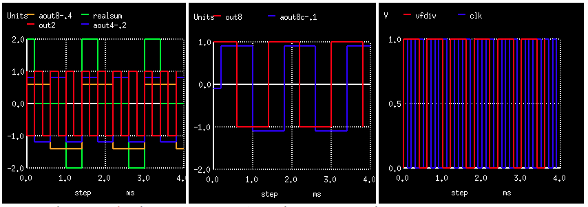
1)The signals vin is Analog and floating and continuous
2)The a2d converts vin into clk which is a Digital, binary,event driven signal
3)The dff preforms the D flip flop function with output div2_out ,div4_out,and div8_out
4)The d2real converts div2_out into out2 which is Real and is floating event driven
5)The real2V converts out4 into Analog and floating and continuos
6)The realZDelay delays out8 using div2_out
6)The fdivider frequency divides the clk
=====================================================
Counter_Translates_between_Real_Digital
v1 vin 0 0.0 pulse(0 1 1n 1n 1n .1m .2m) $ PULSE( VINIT VPULSE TDELAY TRISE TFALL PWIDTH PERIOD )
r1 vin 0 1k
abridge1 [vin] [clk] a2d
adiv2 div2_out clk NULL NULL NULL div2_out dff
adiv4 div4_out div2_out NULL NULL NULL div4_out dff
adiv8 div8_out div4_out NULL NULL NULL div8_out dff
abridge2 div2_out NULL out2 d2real
abridge4 div4_out NULL out4 d2real
abridge8 div8_out NULL out8 d2real
abridge3 out4 aout4 real2V
abridge5 out8 aout8 real2V
az_delay out8 div2_out aout8d realZDelay
abridge6 aout8d aout8c real2V
afdiv clk vfdiv fdivider
.model a2d adc_bridge $ "analog-to-digital node bridge" in_a out_d
.model dff d_dff $ d-type flip flop
.model d2real d_to_real (zero=-1 one=1) $ digital to real with enable in,en,out
.model real2V real_to_v $ gain block for event-driven real data in,out
.model realZDelay real_delay
.model fdivider d_fdiv( div_factor = 3 high_cycles = 2 )
.control
tran 1e-5 4e-3
*plot vin clk
let realsum = aout4+ aout8
plot out2 aout4-.2 aout8-.4 realsum
plot out8 aout8c-.1
plot vfdiv clk
.endc
.end
.end
* source /Users/don_sauer/Downloads/SI_Lib/Tests.cir
=====================END_OF_SPICE=======================
=========================Testing_Digital_Logic=========================================
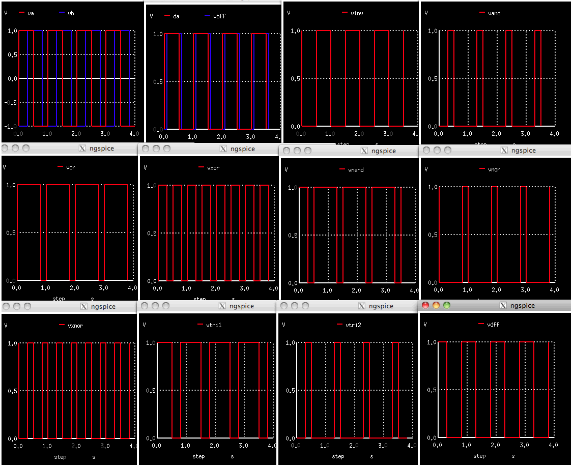
1)The signals VA , VB and Vcc are Analog and floating and continuous
2)The adc_buff2 model converts VA into dA which is a Digital, binary,event driven signal
3)The buff1 model allows real time delays
4)The normal invert, and, nor, xor, tristate and their inverted functions are included
=====================================================
Testing_Digital_Logic
vinA VA 0 0.0 PULSE(-1 1 1m 1m 1m .5 1 )
vinB VB 0 0.0 PULSE(-1 1 .3 1m 1m .5 1 )
Vcc Vcc 0 1
aadc2 [VA] [dA] adc_buff2
aadc3 [VB] [dB] adc_buff2
aadc4 [Vcc] [dHi] adc_buff2
abuf dA vbff buff1
ainv dA vinv inv1
aand [dA dB] vand and1
anand [dA dB] vnand nand
aor [dA dB] vor or1
anor [dA dB] vnor nor12
axor [dA dB] vxor xor3
axnor [dA dB] vxnor xnor3
atri1 dA dB vtri1 tri7
atri2 dA dB vtri2 tri7
apup vtri1 pullup1
apdwn vtri2 pulldown1
adff vdff vxnor NULL NULL NULL vdff dff
asrff vxnor dB vdff NULL NULL NULL vsrff srff
afdiv vdff vfdiv divider
aand2 [dA dHi] vand2 and1
.model adc_buff2 adc_bridge()
.model nand d_nand ( rise_delay=1e-5 fall_delay=1e-5)
.model buff1 d_buffer( rise_delay = 0.9e-1 fall_delay = 0.9e-1 input_load = 0.5e-12)
.model inv1 d_inverter(rise_delay = 0.5e-9 fall_delay = 0.3e-9 input_load = 0.5e-12)
.model and1 d_and( rise_delay = 0.5e-9 fall_delay = 0.3e-9 input_load = 0.5e-12)
.model or1 d_or( rise_delay = 0.5e-9 fall_delay = 0.3e-9 input_load = 0.5e-12)
.model nor12 d_nor( rise_delay = 0.5e-9 fall_delay = 0.3e-9 input_load = 0.5e-12)
.model xor3 d_xor( rise_delay = 0.5e-9 fall_delay = 0.3e-9 input_load = 0.5e-12)
.model xnor3 d_xnor( rise_delay = 0.5e-9 fall_delay = 0.3e-9 input_load = 0.5e-12)
.model tri7 d_tristate(delay = 0.5e-9 input_load = 0.5e-12 enable_load = 0.5e-12)
.model flop1 d_dff( clk_delay = 13.0e-9 set_delay = 25.0e-9 reset_delay = 27.0e-9 ic = 2
+ rise_delay = 10.0e-9 fall_delay = 3e-9)
.model dff d_dff
.model flop7 d_srff( clk_delay = 13.0e-9 set_delay = 25.0e-9 reset_delay = 27.0e-9 ic = 2 rise_delay = 10.0e-9
+ fall_delay = 3e-9)
.model srff d_srff
.model pullup1 d_pullup(load = 20.0e-12)
.model pulldown1 d_pulldown(load = 20.0e-12)
.model divider d_fdiv(div_factor = 3 high_cycles = 2
.control
destroy all
tran 1e-3 4
plot VA VB
plot dA vbff
plot vinv
plot vand
plot vor
plot vxor
plot vnand
plot vnor
plot vxnor
plot vtri1
plot vtri2
plot vdff
*plot vfdiv
display
.endc
.end
* source /Users/don_sauer/Downloads/SI_Lib/Tests.cir
=====================END_OF_SPICE=======================
ngspice 10 -> print dHi
dhi = 1.000000e+00
====================Testing_Digital_FlipFlops=======================
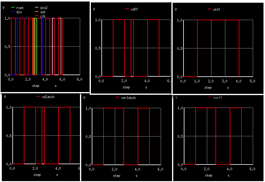
1)The signals Vclk , Vdata ,Vdata2 ,Vset, and Vrest are Analog and floating and continuous
2)The adc_buff2 model converts Vclk into clk which is a Digital, binary,event driven signal
4)The normal D flipflop,toggle flipflop, D latch,and DSR latch are included
=====================================================
Testing_Digital_FlipFlops
vclk Vclk 0 0.0 PULSE(-1 1 1m 1m 1m 0.5 1 )
vdata Vdata 0 0.0 PULSE(-1 1 .7 1m 1m 1 3 )
vdata2 Vdata2 0 0.0 PULSE(-1 1 4.8 1m 1m 1 3 )
vset Vset 0 0.0 PULSE(-1 1 2.55 1m 1m 0.15 60 )
vrset Vrset 0 0.0 PULSE(-1 1 2.75 1m 1m 0.15 60 )
Vcc Vcc 0 1
aadc2 [Vclk] [clk] adc_buff2
aadc3 [Vdata] [din] adc_buff2
aadc33 [Vdata2] [din2] adc_buff2
aadc4 [Vset] [set] adc_buff2
aadc5 [Vrset] [rset] adc_buff2
atoggle din clk set rest vtff vtffn dtff
asrff din din2 clk set rset vsrff vsrffn dsrff
adlatch din clk set rset vdlatch vdlatchn ddlatch
asrlatch din din2 clk NULL NULL vsrlatch vsrlatchn dsrlatch
.model adc_buff2 adc_bridge()
.model dff d_dff
.model dtff d_tff
.model dsrff d_srff
.model ddlatch d_dlatch
.model dsrlatch d_srlatch
.model latch2 d_srlatch( sr_delay = 13n enable_delay = 22n set_delay = 25n reset_delay = 27n ic = 2 rise_delay = 10n fall_delay = 3n)
.model flop1 d_dff( clk_delay = 13n set_delay = 25n reset_delay = 27n ic = 2 rise_delay = 10n fall_delay = 3n)
.model latch1 d_dlatch(data_delay = 13n enable_delay = 22n set_delay = 25n reset_delay = 27.0n ic = 2 rise_delay = 10.0n fall_delay = 3n)
.model flop3 d_tff( clk_delay = 13n set_delay = 25n reset_delay = 27n ic = 2 rise_delay = 10n fall_delay = 3n t_load = 0.2p)
.model flop7 d_srff( clk_delay = 13n set_delay = 25n reset_delay = 27n ic = 2 rise_delay = 10n fall_delay = 3n)
.control
destroy all
tran 1e-3 6.1
plot clk din set rset din2
plot vdff
plot vtff
plot vsrff
plot vdlatch
plot vsrlatch
display
.endc
.end
* source /Users/don_sauer/Downloads/SI_Lib/Tests.cir
=====================END_OF_SPICE=======================
======================FREQ_PHASE_DETECTION============================
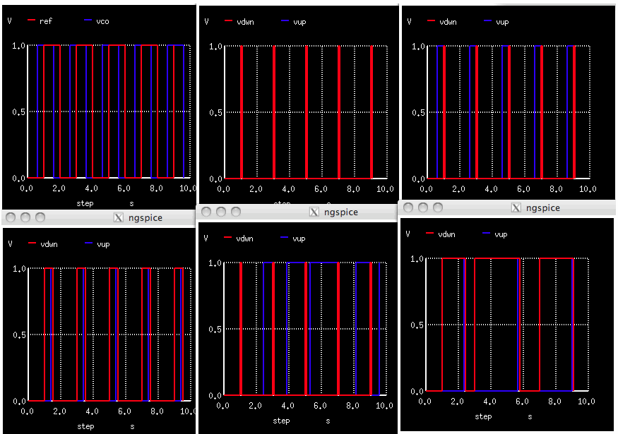
1)Set Up Vref2 and Vvco2 to have their frequencies set by Vf1 and Vf2 and phases by Vp1 and Vp2
2)The analog signals Vref2 and Vvco2 are converted to digital ref and vco using adc_buff2
3)The delay of buff1 sets the min pulse width at the outputs Vdwn and Vup
4)Using standard d_dff, d_and, and d_buffer models
5)The Alter statement allows all the frequency and phases to be test on one simulation
=================================
FREQ_PHASE_DETECTION
*
* NULL
* _____|____ ___
* VCC _| D S Q |_______________________|DWN|
* | 1 | | ____ |___|
* ___ | | |__| \ RS ___
* |REF|___|CLK RS NQ|_ | 3 \____|TAU|_ RS2
* |___| |__________| __| / |___| |
* | | |___/ |
* |______/|\_________________|
* _____|____ | ___
* VCC_| D RS Q |__|____________________|UP |
* | | |___|
* ___ | |
* |VCO|__|CLK NS NQ|_
* |___| |__________|
* |
* NULL
.Options ITL1=1000 ITL2=1000
vt Vt 0 PWL ( 0 0 20 20)
Vf1 Vf1 0 DC = 0.5
Vp1 Vp1 0 DC = 0.5
Bref2 Vref2 0 V = 5*u(sin(2*3.14*(V(Vf1)*V(Vt)- V(Vp1) )))
Vf2 Vf2 0 DC = 0.5
Vp2 Vp2 0 DC = 0.5
Bvco2 Vvco2 0 V = 5*u(sin(2*3.14*(V(Vf2)*V(Vt)- V(Vp2) )))
vref Vref 0 0.0 PULSE( 0 5 .2 9p 9p 1 2 )
vvco Vvco 0 0.0 PULSE( 0 5 .5 9p 9p 1 2 )
Vcc Vcc 0 0.0 PULSE( 0 5 .1 9p 9p 50 200 )
aadc2 [Vref2] [ref] adc_buff2
aadc3 [Vvco2] [vco] adc_buff2
aadc4 [Vcc] [vHi] adc_buff2
ainv dHi vLo inv1
adff1 vHi ref NULL vrs2 vdwn vdwn2 dff $ din clk set rset vdff vdffn
adff2 vHi vco NULL vrs2 vup vup2 dff
aand3 [vdwn vup vHi] vrs and
abuf vrs vrs2 buff1
ainv2 vnrs vnrs2 inv1
.model adc_buff2 adc_bridge()
.model inv1 d_inverter
.model dff d_dff
.model and d_and
.model buff1 d_buffer( rise_delay = 0.1 fall_delay = 0.9e-1 input_load = 0.5e-12)
.control
destroy all
tran 10m 10 0 1m
plot vdwn vup title texttest
alter Vp2 DC = .3
tran 10m 10 0 1m
plot ref vco
plot vdwn vup
alter Vp2 DC = .7
tran 10m 10 0 1m
plot vdwn vup
alter Vf2 DC = .7
tran 10m 10 0 1m
plot vdwn vup
alter Vf2 DC = .3
tran 10m 10 0 1m
plot vdwn vup
* plot all
* show device vref $list device states
* showmod models d_and $prints out model parameters
echo $plots
display
.endc
.end
* ngspice
* source /Users/don_sauer/Downloads/SI_Lib/Tests.cir
=====================END_OF_SPICE=======================
========================Adjustable_Oscillators==========================================

1)Using an analog control signal vcntl to frequency adjust sine, triangle, and square Oscillators
2)Internal control arrays and frequency arrays do mapping of control voltages to output frequencies
3)All signals are analog
=================================
Testing_adjustable_Oscillators
vtime vt 0 pwl( 0 0 1 1)
Bcntl vcntl 0 V = V(vt)
asine vcntl vsinout in_sine
atri vcntl vtri ramp1
apulse vcntl vpulse pulse1
adigOsc vcntl dout var_clock
.model in_sine sine( cntl_array = [0 .2 .5 1] freq_array=[10 50 100 30] out_low = -5.0 out_high = 5.0)
.model ramp1 triangle(cntl_array = [0 .2 .5 1] freq_array=[10 50 100 30] out_low = -5.0 out_high = 5.0 duty_cycle = 0.9)
.model pulse1 square( cntl_array = [0 .2 .5 1] freq_array=[10 50 100 30] out_low = 0.0 out_high = 4.5 duty_cycle = 0.2
+ rise_time = 1e-6 fall_time = 2e-6)
.model var_clock d_osc( cntl_array = [0 .2 .5 1] freq_array =[10 50 100 30] duty_cycle = 0.4 init_phase = 180.0
+ rise_delay = 10e-9 fall_delay=8e-9)
.control
destroy all
tran 1e-3 1
plot vt
plot vsinout
plot vtri
plot vpulse
plot dout
display
.endc
.end
* source /Users/don_sauer/Downloads/SI_Lib/Tests.cir
=====================END_OF_SPICE=======================
========================TRUE_Mixed_SIGNAL===================================
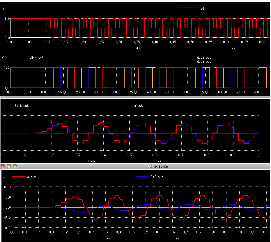
1)Converts analog signal 1 to digital enable
2)Looks like using nand gate to create clk
3)Divide clk by eight at div8_out
4)Converts digital div8_out to real Filter_In
5)LowPass Filter using Z transforms to produce real Filter_out
6)Converts Real filter_out to analog a_out
7)Analog filter is using a OP_Amp Model XLPF1 which is limited like a real opamp
=================================
*
* ___________________________________________________________
* | enable |
* | div2_out dic4_out div8_out |
* abridge1 | __________ __________ __________ |abridge2
* r1 1 |\ | ___ | ______ | | ______ | | ______ | | ___
* __/\ /\ /\______| \_|__| \ _ | |adiv2 |_| | |adiv4 |_| | |adiv8 |_| |__| \
* _|_ \/ \/ _|_ | / | \/ \_ |_| | | |_| | | |_| | | | \__
* /// /_ \ |/ ___|aclk/\_/ | |______| | |______| | |______| |______| / |
* |/ \_/| | |___/ | /|\ | /|\ | /|\ |___/ |
* \___/ | clk |______| |_______| |_______| |
* _|_ v1 |____________| Filt_in |
* \\\ | _____________________________________________________|
* | | X_FILTER
* | | ____________ _____||______
* | |_____| | Filt_out | || |
* | | IN | | |
* | | OUT|___ abridge3 |_/\ /\ /\_|rlpf2
* |_______________| CLK | | | \/ \/ |
* |____________| | |\ a_out | |\ |
* |___| \__/\ /\ /\_|____| \ |
* | / \/ \/ | \ | lpf_out
* |/ rlpf1 | \___|__
* | /
* ___|+ /XLPF1
* _|_ | /
* \\\ |/
* ______ ______
* filt_in |an2a | |an2b |
* ___________________________\|1.0 |__ ____________________________\|1.0 |__
* | ______ /|______| | | ______ /|______| |
* | |an1a | | | |an1b | |
* |_____________\|2.0 |__ |x2a |_____________\|2.0 |__ |
* | /|______| | | filt_2 | /|______| | |
* | | x1a clk | filt_1 clk | clk | x1b clk |
* | ______ __|___ | ___|__ | ______ ___|__ | ______ x0b __|___ | ___|__ |x2b ___|__
* | |an0a | |az0a | | |az1a | | |az2a | |az1a | | |an0b | |az0b | | |az1b | | |az2b |filtout
* ___|__\|1.0 |___\| Z |_|___\| Z |_|____\|0.125 |_\| Z |__|_\|1.0 |____\| Z |_|___\| Z |_|_____\| Z |_
* /|______| | /|______| | /|______| | /|______| /|______| /|______| | /|______| | /|______| | /|______|
* | | | | | |
* | x0a | ______ | | | ______ |
* | | |ad1a | | | | |ad1 | |
* | ______ |___|.5625 |/__| | ______ |___|1.00 |/__|
* | |ad0a | |______|\ | | |ad0 | |______|\ |
* |__|.75 |/________________| |__|-.34 |/________________|
* |______|\ |______|\
*
TRUE_Mixed_SIGNAL
v1 1 0 0.0 pulse(0 1 1e-4 1e-6)
r1 1 0 1k
*
abridge1 [1] [enable] atod
aclk [enable clk] clk nand
adiv2 div2_out clk NULL NULL NULL div2_out dff
adiv4 div4_out div2_out NULL NULL NULL div4_out dff
adiv8 div8_out div4_out NULL NULL NULL div8_out dff
abridge2 div8_out enable filt_in node_bridge2
xfilter filt_in clk filt_out dig_filter
abridge3 filt_out a_out node_bridge3
xlpf 0 oa_minus lpf_out opamp
rlpf1 a_out oa_minus 10k
rlpf2 oa_minus lpf_out 10k
clpf lpf_out oa_minus 0.01uF
.model atod adc_bridge $ "analog-to-digital node bridge" in_a out_d
.model nand d_nand (rise_delay=1e-5 fall_delay=1e-5)
.model dff d_dff $ d-type flip flop
.model node_bridge2 d_to_real (zero=-1 one=1) $ digital to real with enable in,en,out
.model node_bridge3 real_to_v $ gain block for event-driven real data in,out
.subckt dig_filter filt_in clk filt_out
an0a filt_in x0a n0 $ plot xfilter.x0a xfilter.x1a xfilter.x2a
az0a x0a clk x1a zm1 $ plot xfilter.x0a xfilter.x1a
az1a x1a clk x2a zm1
an1a filt_in x1a n1
an2a filt_in x2a n2
ad0a x2a x0a d0a
ad1a x2a x1a d1a
az2a x2a filt1_out g1
az3a filt1_out clk filt2_in zm1
an0b filt2_in x0b n0
an1b filt2_in x1b n1
an2b filt2_in x2b n2
az0b x0b clk x1b zm1
az1b x1b clk x2b zm1
ad0 x2b x0b d0b
ad1 x2b x1b d1b
az2b x2b clk filt_out zm1
.model n0 real_gain (gain=1.0) $ gain block for event-driven real data in,out
.model n1 real_gain (gain=2.0)
.model n2 real_gain (gain=1.0)
.model g1 real_gain (gain=0.125)
.model zm1 real_delay
.model d0a real_gain (gain=-0.75)
.model d1a real_gain (gain=0.5625)
.model d0b real_gain (gain=-0.3438)
.model d1b real_gain (gain=1.0)
.ends dig_filter
.subckt opamp plus minus out
r1 plus minus 300k
a1 %vd (plus minus) outint lim
r3 outint out 50.0
r2 out 0 1e12
.model lim limit (out_lower_limit = -12 out_upper_limit = 12 fraction = true limit_range = 0.2 gain=300e3)
.ends opamp
.control
tran 1e-5 1e-3
save all
display
plot v(1)
plot a_out
plot a.xlpf.a1#branch_1_0
plot abridge3#branch_1_0
plot lpf_out
plot xlpf.outint
plot filt_in lpf_out
plot clk div2_out div4_out div8_out
plot xfilter.x1a
.endc
.end
* source /Users/don_sauer/Downloads/SI_Lib/Tests.cir
=====================END_OF_SPICE=======================
=============Simple_measurement_examples===============
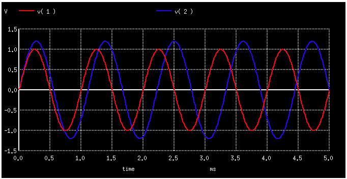
1)Measure methods for processing waveforms
2)Looks like sensitive to style
=================================
Simple measurement examples
vac1 1 0 DC 0 sin (0 1 1k 0 0)
vac2 2 0 DC 0 sin (0 1.2 0.9k 0 0)
r1 1 0 1k
.tran 10u 5m
.measure tran tdiff TRIG v(1) VAL=0.5 RISE=1 TARG v(1) VAL=0.5 RISE=2
*time between v(1) 0.5 V first rising (TRIG) versus 0.5 V again second rising slope
.measure tran tdiff2 TRIG v(1) VAL=0.5 RISE=1 TARG v(1)) VAL=0.5 RISE=3
*time between v(1) 0.5 V first rising slope versus reach 0.5 V third rising slope
.measure tran tdiff3 TRIG v(1) VAL=0.5 RISE=1 TARG v(1) VAL=0.5 FALL=1
.measure tran teval WHEN v(2)=0.7 CROSS=LAST
*when v(2) crosses 0.7 V for last time (any slope).
.measure tran yeval FIND v(2) WHEN v(1)=-0.4 FALL=LAST
*returns(y) from v(2) when v(1) equals -0.4, v(1) falling last time.
.measure tran yeval2 FIND v(2) WHEN v(1)=v(3) FALL=2
*returns (y) from v(2) when v(1) crosses v(3),v(1) falling second time.
.measure tran yeval3 FIND v(2) AT=2m
*returns (y) v(2) at time 2 ms (given by AT=time).
.measure tran ymax MAX v(2) from=2m to=3m
*returns maximum v(2) inside the time interval between 2 ms and 3 ms.
.measure tran tymax MAX_AT v(2) from=2m to=3m
*returns time max v(2) between 2ms and 3ms.
.measure tran ypp PP v(1) from=2m to=4m
*returns peakpeak v(1) between 2ms and 4ms.
.measure tran yrms RMS v(1) from=2m to=4m
*returns rms v(1) inside between 2 ms and 4 ms.
.measure tran yavg AVG v(1) from=2m to=4m
*returns average v(1) between 2 ms and 4 ms.
.measure tran yint INTEG v(2) from=2m to=3m
*returns area under v(2) between 2 ms and 3 ms.
.param fval=5
.measure tran yadd param='fval + 7'
*will evaluate expression fval + 7 and return the value 12.
.measure tran tdiff TRIG AT=1m TARG v(2) VAL=-0.8 CROSS=3
.meas tran bw_chk param='(tdiff < tdiff3) ? 1 : 0'
*return 1 in bw_chk, if tdiff < vout_diff.
.measure tran vtest find par('(v(2)*v(1))') AT=2.3m
*will return product of the two voltages at time point 2.3 ms.
.param vp=.5
.measure tran inv_delay2 TRIG v(1) VAL='vp/2' TD =1m FALL=1 TARG v(2) VAL='vp/2' RISE=1
.meas tran test_data1 TRIG AT=1m TARG v(1) VAL='vp/2' RISE=3
.meas tran out_slew TRIG v(1) VAL='0.2*vp' RISE=2 TARG v(2) VAL='0.8*vp' RISE=2
.param inv_delay=0.2
.meas tran delay_chk param = '(inv_delay < 100m)?1:0'
.meas tran skew WHEN v(1) =0.3
.param skew_meas=0.2
.meas tran skew2 WHEN v(1) = skew_meas
.meas tran skew3 WHEN v(1) =skew_meas FALL=2
.meas tran skew4 WHEN v(1) =skew_meas FALL=LAST
.meas tran skew5 FIND v(1) AT=2m
.param dfall=1m
.param period=3m
.meas tran v0_min MIN v(1) from='dfall' to='dfall+period'
.meas tran v0_avg AVG v(1) FROM='dfall' TO='dfall+period'
.meas tran v0_integ INTEG v(1) FROM= ' dfall' TO = 'dfall +period'
.meas tran v0_rms RMS v(1) FROM= ' dfall' TO= 'dfall+period'
.control
run
plot v(1) v(2)
.endc
.end
* source /Users/don_sauer/Downloads/SI_Lib/Tests.cir
=====================END_OF_SPICE=======================
tdiff = 1.000000e-03 targ= 1.083343e-03 trig= 8.334295e-05
tdiff2 = 2.000000e-03 targ= 2.083343e-03 trig= 8.334295e-05
tdiff3 = 3.332812e-04 targ= 4.166242e-04 trig= 8.334295e-05
teval = 4.88982e-03
yeval = 7.586686e-01
yeval2 = 9.705079e-01
yeval3 = -1.140899e+00
ymax = 1.199850e+00 at= 2.502800e-03
tymax = 2.502800e-03 with= 1.199850e+00
ypp = 1.999690e+00 from= 2.000000e-03 to= 4.000000e-03
yrms = 7.07113e-01 from= 2.00000e-03 to= 4.00000e-03
yavg = -5.472312e-16 from= 2.000000e-03 to= 4.002800e-03
yint = 1.31162e-04 from= 2.00000e-03 to= 3.00000e-03
yadd = 1.20000e+01
tdiff = 7.957641e-04 targ= 1.795764e-03 trig= 1.000000e-03
bw_chk = 0.00000e+00
vtest = 4.853491e-01
inv_delay2 = -1.422639e-03 targ= 3.712823e-05 trig= 1.459767e-03
test_data1 = 1.040230e-03 targ= 2.040230e-03 trig= 1.000000e-03
out_slew = 1.552708e-04 targ= 1.171220e-03 trig= 1.015949e-03
delay_chk = 0.00000e+00
skew = 4.85173e-05
skew2 = 3.20512e-05
skew3 = 1.46794e-03
skew4 = 4.46794e-03
skew5 = 3.666742e-06
v0_min = -9.998452e-01 at= 1.752800e-03
v0_avg = -3.166828e-16 from= 1.000000e-03 to= 4.002800e-03
v0_integ = 1.71125e-09 from= 1.00000e-03 to= 4.00000e-03
v0_rms = 7.07113e-01 from= 1.00000e-03 to= 4.00000e-0
======================Monte_Carlo=========================================
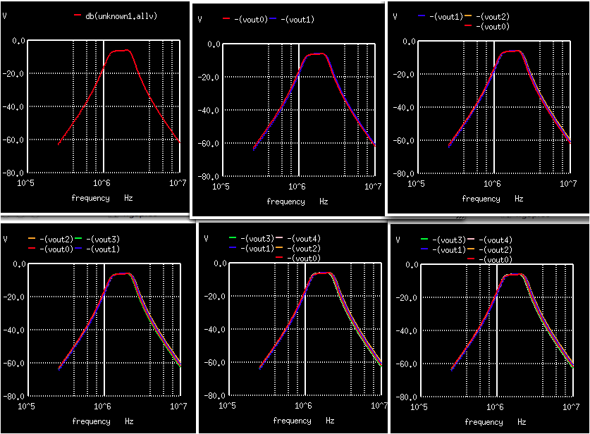
1)Set curplot=new create a new plot named unknown1
2)Set scratch=$curplot store the name as scratch
3)Setplot $scratch makes it the active plot
4)let bwh=unitvec(mc_runs) creates a unitvector within $scratch
5)Several noise functions are defined
6)DoWhile does an alter to all the circuits devices and does AC
7)Measure finds the bandwidth bw of each ac waveform
8)Set run ="$&run" shows how to create a variable from a vector
9)Set dt = $curplot store the current plot to dt
10)Setplot $scratch makes 'scratch' the active plot
11)vout{$run} shows how to create a vout3 string
12){$dt}.v(out) shows how access ac4.v(out)
13)let vout{$run}={$dt}.v(out) adds ac4.v(out) as vout3 into scratch
13)let bwh[run]={$dt}.bw adds the bw into the bwh array in scratch
14)setplot $dt returns the saved plot in dt
15)plot db({$scratch}.allv) plots all plots in scratch
16)print {$scratch}.bwh accesses the bwh array in scratch
=================================
MonteCarlo
V1 N001 0 AC 1 DC 0
R1 N002 N001 141
C1 OUT 0 1e-09
L1 OUT 0 10e-06
C2 N002 0 1e-09
L2 N002 0 10e-06
L3 N003 N002 40e-06
C3 OUT N003 250e-12
R2 0 OUT 141
.control
destroy all
let mc_runs = 5 $ run 5 time
let run = 0 $ use run as index
set curplot=new $ create a new plot
echo $curplot $ unknown1
set scratch=$curplot $ store its name to 'scratch'
setplot $scratch $ make 'scratch' active plot {$scratch}=unknown1
let bwh=unitvec(mc_runs) $ create a unitvec in 'scratch' to store bandwidth bwh data
display
echo $plots
define unif( nom, rvar) (nom + (nom*rvar) * sunif(0))
define aunif( nom, avar) (nom + avar * sunif(0))
define gauss( nom, rvar, sig) (nom + (nom*rvar)/sig * sgauss(0))
define agauss(nom, avar, sig) (nom + avar/sig * sgauss(0))
define limit( nom, avar) (nom + ((sgauss(0) >= 0) ? avar : -avar))
dowhile run < mc_runs $ loop starts here
alter c1 = unif(1e-09, 0.1)
alter l1 = unif(10e-06, 0.1)
alter c2 = unif(1e-09, 0.1)
alter l2 = unif(10e-06, 0.1)
alter l3 = unif(40e-06, 0.1)
alter c3 = limit(250e-12, 25e-12)
ac oct 100 250K 10Meg
meas ac bw trig vdb(out) val=-10 rise=1 targ vdb(out) val=-10 fall=1
echo "bw = $&bw" $ bw = 1.23758E+06
echo "run = $&run" $ run = 4
set run ="$&run" $ create a variable from a vector
echo $plots $ const unknown1 ac1 ac2 ac3 ac4 ..
echo $curplot $ ac4
set dt = $curplot $ store the current plot to dt
echo $scratch $ unknown1
setplot $scratch $ make 'scratch' the active plot
echo $dt $ ac4
echo vout{$run} $ vout3 how to append number to names
let vout{$run}={$dt}.v(out) $ store output vector to plot 'scratch' as vout3
*plot {$dt}.v(out) $ plots ac4.v(out)
let bwh[run]={$dt}.bw $ store bw to vector bwh in plot 'scratch'
setplot $dt $ go back to the previous ac vs frequency plot
let run = run + 1
plot db({$scratch}.allv) $ plot whats in $scratch as ac versus frequency
end $ loop ends here
plot db({$scratch}.allv)
echo
print {$scratch}.bwh $ access vector bwh in {$scratch}=unknown1
.endc
.end
* source /Users/don_sauer/Downloads/SI_Lib/Tests.cir
=====================END_OF_SPICE=======================
bw = 1.238482e+06 targ= 2.391451e+06 trig= 1.152969e+06
run= 0 const unknown1 ac1 vout0
bw = 1.273318e+06 targ= 2.460727e+06 trig= 1.187408e+06
run= 1 const unknown1 ac1 ac2 vout1
bw = 1.322717e+06 targ= 2.500673e+06 trig= 1.177956e+06
run= 2 const unknown1 ac1 ac2 ac3 vout2
bw = 1.198959e+06 targ= 2.351464e+06 trig= 1.152504e+06
run= 3 const unknown1 ac1 ac2 ac3 ac4 vout3
bw = 1.171146e+06 targ= 2.313612e+06 trig= 1.142466e+06
run= 4 const unknown1 ac1 ac2 ac3 ac4 ac5 vout4
--------------------------------------------------------------------------------
Index unknown1.bwh
--------------------------------------------------------------------------------
0 1.238482e+06
1 1.273318e+06
2 1.322717e+06
3 1.198959e+06
4 1.171146e+06
4-15-13-12-16-13
dsauersanjose@aol.com
Don Sauer