*=============Boost_Duty_Cycle_Plots=======================
The Boost Converter is not a large circuit. So it is
not hard to run three identical circuits havin three
different loads at the same time.
=======================================================================
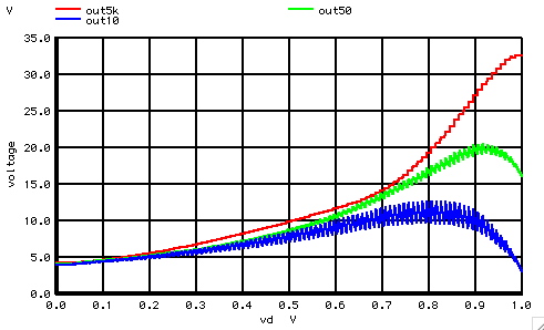
plot out5k out50 out10 vs vd
=======================================================================
Boost_Converter_Loaded
* _ _ _
* ___ / \/ \/ \V1 ___ R1
*|VIN|_| () () |___|\|__|OUT|__/\ /\ /\__
*|___| L1 | |/| |___| \/ \/ _|_
* / S1 | | C1 ///
* _/ ____| D1 |__||__
* _|_ || _|_
* /// ///
The unloaded output of the Boost Converter should come
close to 10 volts at a 50% duty cycle. At 50% of the time,
the switch S1 puts 5volts across the inductor L1.
The inductor is acting like a energy storage device of
E= i^2*L/2. When switch S1 opens, inductor L1
will try and dump that magnetic energy into diode D1.
If the time period for diode D1 is about the same,
inductor L1 can ramp its current down at the same rate
while providing 5volts across it. When the duty cycle of the
diode is small, the inductor L1 needs to raise its voltage to
dump the same stored magnetic energy.
===========Full_Netlist_For_Copy_Paste=======================
Boost_Converter_Loaded
* _ _ _
* ___ / \/ \/ \V1 ___ R1
*|VIN|_| () () |___|\|__|OUT|__/\ /\ /\__
*|___| L1 | |/| |___| \/ \/ _|_
* / S1 | | C1 ///
* _/ ____| D1 |__||__
* _|_ || _|_
* /// ///
VP VP 0 DC 3.141592653589793
VT VT 0 PWL ( 0 0 1m .1m )
VD VD 0 PWL ( 0 0 1m 1 )
VIN VIN 0 DC 5
B1 TRI 0 V = acos( cos(v(VP)*v(VT)*2*1e6) )/v(VP)
B2 VSW 0 V = 2*u( -v(TRI) +v(VD)) -1
B3 V1B 0 V = 5*u( v(VSW) )
*SXXXXXX N+ N- NC+ NC- MODEL <ON><OFF>
R1 VIN V1L 1m
L1 V1L V1 100u
S1 V1 0 VSW 0 SWP
D1 V1 OUT5K DD
C1 OUT5K 0 3u
RL1 OUT5K 0 50K
R2 VIN V2L 1m
L2 V2L V2 100u
S2 V2 0 VSW 0 SWP
D2 V2 OUT50 DD
C2 OUT50 0 3u
RL2 OUT50 0 50
R3 VIN V3L 1m
L3 V3L V3 100u
S3 V3 0 VSW 0 SWP
D3 V3 OUT10 DD
C3 OUT10 0 3u
RL3 OUT10 0 10
.MODEL SWP SW( VT=2.6m VH=.2 RON=10u ROFF=100MEG)
.model DD D( IS=3.15e-18 )
*TRAN TSTEP TSTOP TSTART TMAX ?UIC?
*.tran .01u 1m 0 .01us
*=========Run_Sim============================================
.control
tran .1u 1m 0 .1us
set pensize = 2
plot out5k out50 out10 vs vd
.endc
.end